G. Johanson, WD4NKA
1125 Elgrove Drive
Deltona, Fl.  32725
([email protected] or [email protected])
Return to top
What is it?
What this is, is a triode regenerative detector followed by a single stage audio amplifier.
Very much like the traditional detector and one step of the 20's and 30's. The only real
difference lies in the components themselves, and not even much change there. Just newer
items. The tube, as mentioned above, is a medium mu dual triode, very inexpensive, unless
the audio folks have succeeded in driving the prices out of sight as of this writing.
I had decided to use a conventional single tuned front end on this receiver, which will almost dictate the use of the lower end of the HF spectrum, 160, 80, and 40 metres. I have had great success using this very set-up on 80m. for CW contacts.
Return to top
A Little Background
This receiver took advantage of the drop in component prices toward the end of the 1930s,
and the ensueing post WW2 surplus parts flood. In fact, by 1948, why, for the
price of a meal at a diner, you could purchase most of the components for this receiver,
and the tube. These little receivers were considered to have offered close to
the minimum useable performance for amateur use. My own candid opinion is a little better
than that after having re-strung a couple mid priced receivers from that era. When well
constructed, using solid connections and stiff wire, these little guys are no slouches
on performance.
In the early years of the second decade of the twentieth century just prior to the Great War, it was discovered that if the input of a tube amplifier was allowed to sample some of the output, sensitivity was greatly increased. So too was selectivity enhanced, to a degree. For wireless operators using the Branley Coherers and crystal or chemical detectors, depending wholly upon the strength of the received signal for volume and sensitivity, using a bewildering array of inductances to alternately tune or reject signals, this was a very welcome addition to the state of the art. By 1920, this was the primary receiver in use. The 1937 edition of Terman's Radio Engineering still indicated the regenerative receiver the most efficient form of CW reception. From the standpoint of parts / price / performance, they had no peer. Various schemes of feedback and tuning were employed, alternately enjoying momentary fame, then making room for another method, fading away to still another method. First one tube, then two, then three, then four, and in the case of some broadcast receivers, six tubes were employed as the years went by. By 1933 the arch-typical amateur set-up boasted a National SW-3, or reasonable facimile therof, and a curtain-rod Hartley feeding an off-center fed Zepplin wire . . . . of course. Gernsback, Schnell, and Reinartz tuners were written about, tried, modified, re-modified, and by 1936, just about every conceivable contrivance of regenerative receiver was known. And just about every shortfall was known as well, already being addressed by 1930 in a circuit known as the Superheterodyne, but that's another story.
By the time of the Second World War, the Regenerative had pretty much ceased to be the premier receiver on the bench at most shacks. In fact, even by the late thirties most regens were used as second, or "stand-by" receivers, employed principally in emergency work where they performed with great success, adding much to it's legacy. It was hard to beat for a battery rig, with a small tube count and current draw. In a 1936 issue of QST there is a photo of a regen which was constructed by a non-ham following instructions given over the telephone during a raging flood! By listening to this hay-wired rig built on a pine board, the user was able to receive flood warnings and information that saved his life! Try THAT with a superhet! (the guy must've used an audio tube from his broadcast set.)
After the war, the only regenerating going around was on VHF and UHF with superregenerators, a type of regenerative receiver. Except with beginners, the regen had pretty much gone over the horizon with the sunset. New amateurs were, however, still building these things to tide them over untill they could afford that HQ-139x or get dad's receiver from him after HE upgraded to the newer RME-69. But then, the surplus market exploded and flooded the ham market with pretty good cheap radio equipment. Even in spite of this availability of inexpensive gear, there were still printed in handbooks and magazines many one and two tube regen projects. AND, they were being built. The regenerative receiver remained a great way to learn about receiver construction and theory, and the gratification was almost instant. So in a real, though attenuated sense the regen had survived World War Two.
Much beyond the 1960's as more and more solid state designs encroached upon the average ham's bench, less and less was seen of the little regenerator, although still offered in one form or another from Heathkit to Allied, and from time to time a solid state regen article would appear for the beginner. Into the 1970's, most handbooks had ceased to describe them fully (or accurately) supplimenting the regen with the Direct Conversion Receiver as a beginner's first receiver. There were reasons for this, largely due to the ability to greatly amplify at audio levels without hum and use of a single 9 or 12 volt battery. Solid state DC radios had eclipsed the Regenerative receiver.
Almost.
I had noticed in the early nineties that more and more voices were beginning to call "Foul!!" There has always been a group of regen builders (like me) who were amazed at the technical sleep that seemed to overlay the current literary world, almost like a haze. We noticed that all the handbooks and magazines used the same description " they are cranky", "they emit too much RF", "they are too broad", "they are ineffective detectors", etc., almost as if they actually dreaded the return of the Regenerative receiver worse than the plague. Having built these little DC receivers, all of which can be described as "cranky", "RF generators", "Broadbanded", and even "ineffective" if not constructed correctly, we began to conclude that the regen still had a rightful place along side current modes of reception. It is a fact that a Regen is capable of everything a DC radio can do just as efficiently and economically. The Regen exhibits more sensitivity and requires less audio amplification, greatly reducing the inherent audio distortion products in most "simple" DC receivers. The key phrase here is "When Well Built".
As the nineties (and the internet) progressed, an increasing number of groups began to emerge, reviving many of the old wireless schemes. More awareness of radio's past can be attributed to the likes of the Crystal Set Associations, the Boat Anchor groups, the Glowbug contingent, the Antique Wireless groups, in fact, so much attention is being brought to bear that, wonder of wonders, the commercial producers are back to making regen kits! MFJ and Ten-Tec both offer one.
Now we are in a new millenia, and radio is over one hundred years old. Interest in the Regenerative receiver is still growing, lately thanks to the internet and e-mail groups. As I peruse the various sites on line, I notice NorCal and other groups adapting the regen scheme into other more non traditional environments. And that's the way it should be. Let it grow with the times, and progress. After all, most of our finest ideas are rooted in the misty past.
Return to top
Some Construction Notes
When building any regenerative receiver, it is wise to consider yourself constructing a VFO, because for all intents and purposes you are. The stability is almost entirely determined by the construction of the receiver and all connected peripherals. What makes solid construction even more important is the fact that we are only using one RF stage. Nothing to buffer the detector from the outside world, as it were; even a swinging antenna is capable of destabilising the received signal. DC receivers can suffer from the same shortcomings, so don't worry, they can be overcome.
First and foremost, we need something to shield the controls from the inards of the set, lest the capacity of your very hands affect the tuning. I would suggest to always use a metal face plate, or, at least, put something that you can ground behind that authentic bakelite front panel to shield your components from hand / body capacity. Another idea from the past is to recess your tuning components as far to the rear of the chassis or board as possible, using teflon, lucite, or even hardwood shafts as extensions thru the front panel. If you use a wooden board (which is a pretty good choice to build upon, actually), consider a couple of techniques from the 1930's: Raise the wood on short legs, and mount a metal ground plate on the bottom side. This way all the grounding points can be drilled thru the wood and soldered to the common ground plate. Or, cut a hole slightly smaller than the plate, say, half or so the size of the board, and mount the plate atop the hole (see picture). This gives you some of the advantages of the metal chassis, in that you can use terminal strips with direct grounding, punch out a tube socket hole for the tube mount and use conventional under chassis wiring technique. Many of those old rigs were actually built upon masonite, with wood slat sides, creating a box of sorts, with a metal plate on the underside of the masonite. Components were wired under the masonite, with only the tubes, transformers, variable capacitors, etc, on the top. B+, Filament and Ground connections were accessed by terminal connections drilled right thru the wood sides. Masonite was used as a front panel, as well, but, again, I would at least line the back with an aluminum plate for shielding concerns.
Another suggestion is to build the power supply as a separate unit. This will go a long way in keeping A.C. hum at bay. Speaking of the power supply, although I did not include a schematic in the circuit page, largely because any one will work, I do have a suggestion if you have a hard time finding power transformers much over 90 v. Use two filament transformers, connected secondary to secondary. The resulting combination will provide both the filament and the plate voltages. What should appear at the output is 120v.a.c., which can be then rectified thru a 400v PIV silicone diode, then filtered with a 250v 40uF filter cap, and then thru the primary of an old audio plate to voice coil transformer or similar choke, filtered past another 250v / 40 uF cap, and across a 30k ohm / 5 watt resistor for bleed. All parts can be had at Radio Shack, the whole thing built into one of their project boxes for about 30 bucks. This is a worthwhile project in itself because you can use it for any number of small tube projects. But don't go trying to key 110v d.c. relays with it, you'll smoke it sure! Keep the current down to, say 50mA, which at 120v under load should give you 6 watts max. That'll do for a one, two, or sometimes 3 tube receiver project, or maybe a QRP transmitter.
Return to top
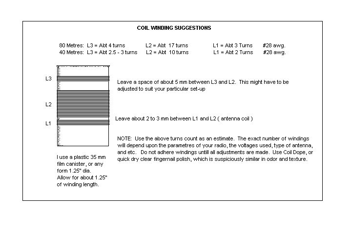
Winding the Coils
A whole lot of lattitude is allowed here. So much of how you wind your coils, how many turns, diameter, spacings, etc., depend upon your circuit parametres. However, here are some good guestimations that should get you somewhere in the ballpark. Click on the sub-title, and you can copy the info. I usually use a 35 mm plastic film canister for a form, but any non conductive form can be used, really. I have heard the discussions about PVC, and really, unless you are using it for high power finals where heat is a very real problem, there no problem.
Return to top
Circuit Description and Details
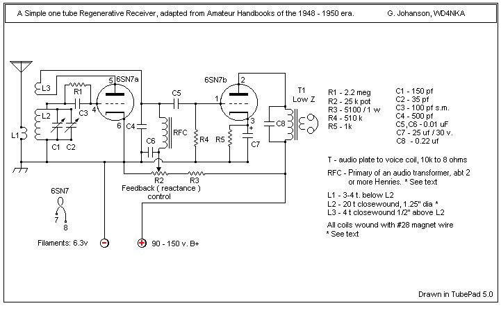
Essentially, the antenna (L1) feeds the signal to L2 where it is tuned, and passed on for detection. L3 provides feedback necessary for regeneration. The amplified signal is passed on to the next stage for audio amplification, the RF being bled off by C6, and the B+ being blocked by C5. R5 and C7 provide biasing for the audio amp, and the impedance of the output therof is converted to eight ohms by the transformer T1. The primary can have a .2uF cap wired across the primary to keep out the sonics. Of course, you can omit T1 and put the good ol' Baldies in series with the B+ to the audio, but lot's of folks have problems with live B+ on the headsets where reaching up and grabbing them can produce quite a surprise, if you are using appreciable voltages. Besides, 8 ohm headphones are easier and cheaper to find. The tube used in this example is a 6SN7, but throughout the mid to late 1930s and into the 1940s, several different dual triodes were used. In 1938, QST published a one tube "modern" regen sporting a 6F8G and used transformer coupling between detector and audio stages. This can be done here as well with a 3:1 audio interstage transformer. The 6SN7 / 6SL7 type tubes were used in handbooks into the 1950's, whereas the 6U8A triode-pentode became widely used. The 12AX7 or 12AU7 dual triodes can be seen used clear up into the 1970's.
Return to top
Candid Comments on how it works
I feel a little funny trying to describe something that has been described about a zillion times
before, because when I make a mistake, the e-mail bin gets filled with fingers pointing at me,
and I have to come up with an excuse for the oversight. As old as this circuit is, I have read
many different explanations as to how they work. But as the old order Amish Elders used to say:
"Von ting shur - - i-tvorks" ( Transl: "One thing sure, it works.") Mein Platt ist nicht so gut.
In verrrry basic language so that even I can understand, it goes something like this: (As already mentioned above) the signal, conducted thru the antenna coil L1, is tuned thru L2. Due to the grid leak biasing the grid to an average negative potential (the resistor and the capacitor makes the grid work) this signal regulates the electron flow of the tube ( more properly called Valve ) thus producing an amplified version of itself at the output. This is how basic amplification works in a tube. If the story ended there, you would have . . . . well . . . . a very broadbanded, somewhat mediocre receiver that needs a whopping whole lot of signal for you to really hear very much. In fact, I can remember when Hi-Fi AM receivers were not much more than that. Instead of the grid leak, there would be a diode or two, or four, which would rectify the signal, and feed it into the tube / valve, and give fairly good dynamic sound thru a good audio amp and speaker arrangement. But that signal was from a local broadcast station not more than 50 miles away, if that even.
But what about a weak signal from two thousand miles away? Enter Regeneration. It was discovered over eighty years ago that if some of the output of that valve were to be fed back to the input, it would re-amplify, increasing the amplified signal. If allowed to repeat, it would build up a very weak signal at the input to where it could be heard easily at the output.
So, why not just continue to feed the signal back indefinately? Well, theres just one little snag to all this. As the signal increases, the input resistance decreases to the point that the valve sets up it's own oscillation at the frequency the input is tuned to. The more the feedback, or regeneration, the louder the oscillation. In fact, this type of oscillator is known as an "Armstrong Oscillator", in honour of the man whom most agree first developed this method, and, for that matter, developed the receiver itself. But that's another story.
The point is, we control the amount of feedback. The receiver is adjusted to the correct level corresponding to what the listener requires. That's really about all there is to it. The behaviour of a regenerative detector can be described as, well, interesting. Let me point out firstly that ALL detector types are interesting in their own rights, posessing good and bad qualities. We use them in accordance to what those desired features provide under the conditions in which they will do service. In the case of the regenerative detector, the desired features are sensitivity, selectivity, and low parts count. Especially sensitivity and low parts count. The drawback is stability, which can be overcome by understanding the nature of the beast. At this point, it suffices to know that all RF circuits exhibit their highest gain and greatest selectivity, consequently the most stability at the lowest frequencies. The trick to a regen is to keep it operating at the lowest frequency possible. I would not, for a simple single stage regen such as is described here, go higher than 8 mc. At this point, in my estimation, the circuit begins to live up to it's much mis-applied descriptions of being cranky and instable. Sure, they operated these things well beyond 28 mc in the 1920's, but I bet it wasn't easy.
So that's kind of how it works in street level terms. The bottom line is: always operate any circuit in the element for which it was designed. Regenerative receivers are great for low frequency use. A good example is the tunable regenerative detector used in the Regenerodyne Project.
There's nothing really critical about the layout beyond the normal common wiring proceedures: Short wiring lengths (within reason), keeping all frequency determining devices away from heat producing elements, shielding when possible, especially the front panel, keeping the grid leak as far from any a.c. bearing wiring as you can. I heartily endorse the out-board power supply, and advise using a shielded box to contain it in, grounding the box to a ground point on the receiver itself. This goes a long way in cleaning up hum pickup.
Again, I stress using non conductive extention shafts for most controls, most importantly the variable capacitors. Also, if you can find a vernier dial, this helps a whole lot with these receivers.
Most of the Old Timers built rather symmetrically, and even used the schematic layout as a sort of guide. Boy, we don't do that anymore ! But take the que: especially on a wooden breadboard. Evenly laid out tubes and coils really look nice. And so do 90 degree bends, when you must bend wire. Beyond this, there is really a lot of freedom in your layout. I would suggest securing a copy of an old QST from the early 1930's and looking over the photos. You can garnish valuable info on what the builders of the past did, and great insights on why. You might be surprised at how entertaining those old rags are even today!
Return to top
Set-up and Operation
Setting up and operating a regenerative receiver of any type is simple for the most part. You want to make certain precautions, thought. First thing I always look for is a direct air conditioning draft from an overhead vent. Man, a sudden change in temperature can be annoying as the thermal change slides you up and down the band. Covered rigs are less prone to this, but none the less, seek a fairly stable place to operate. Locate a good ground source. This may or may not be absolutely essential, but it can help, and is a safety feature as well. Make sure you don't have a computer too near the receiver. They are noise generators. In fact, the colourbust fequency of most colour TVs are in the 80m. ham band, so lots of stuff generates from even your TV set. ( Huh, TVI in reverse!)
Your antenna should be as rigid as possible. I am a big believer in an indoor wire for a receive antenna. Your regen is extremely sensitive, and does not need a huge resonant antenna. In fact, a resonant antenna provides a very low resistance when center fed, like a dipole, and this low impedance can load a simple regen to the point where it can't oscillate, producing a dead spot at the resonant point. A simple variable cap in series with the antenna line can be included to add enough reactance to prevent this from occuring. A floppy antenna presents a varying load to a simple regen, and can vary the tuning, producing instable reception. I use a window screen sometimes, with no problem hearing what I want to hear. Note that a very loud (strong) signal can drive your grid into a block, and desense your receiver, even if not in your passband. Therefore, a smaller receiving antenna can actually act as a gain control of sorts, and make operating much more pleasant. Experiment with this.
Operation is easy. After installation, turn on the set. Let it warm a minute. Put on the headsets and tune the regen control until you hear a rushing sound. Don't go much further beyond this sound: it indicates the set is oscillating. If you do not hear this sound, make sure your feedback coil (L3) is wound the same direction as the rest of the coils. With the receiver just beyond the oscillation point (that rushing sound) connect the antenna. If the rushing sound stops, the antenna is loading the detector, which at this point is fine. Advance the feedback further to re-establish regeneration and tune the dial, listening for heterodynes. If you wound the coils close to my specs, you should be pretty much on the band, give or take a few hundred kc. If you never get oscillation at all, recheck the wiring. Especially the grid portion of the detector stage. Sometimes, these sets will only oscillate when the antenna is connected, so check that out as well. If a set fails to oscillate and the windings check out, you will need to either increase the winds of L3, or decrease the space between them (increase coupling). While I think of it, oscillation should never just "plop" on. It should glide nicely into regeneration. This is usually controlled by feedback coupling or the regeneration control's value. 25- 50k ohms is typical in this type of detector (R2). None of the parts are critical, so I have every confidence you will have a working regen you can be proud of quicker than you can say " 73, OM!"
Using this radio takes a little getting used to. For one, since the detector is also the primary RF stage and tuning device, when you change the feedback setting, the frequency will change to some degree. The old timers took that in stride, in fact, it can be used to advantage as a fine tune control of sorts. Different frequencies will have different feedback settings, and as the frequency gets higher, this is more pronounced. One of the reasons why I tend to keep regens on lower frequencies, like 160, 80, and 40 m.
It is possible to spot your frequency on another receiver by tuning the detector to oscillation (advancing the feedback into oscillation) and finding your signal on the other receiver. Just bring the regen's antenna wire near the receiver, and sufficient signal to tune can be picked up by the second receiver. Another way is with a xtal oscillator. If you have a crystal, just use a simple oscillator, and set it somewhere in the same room. Tune in the oscillator, and you know where you're at. Too close, and the xtal oscillator will block your detector, so keep the signal attenuated.
Here's another gimmick I have done in a pinch to get an idea where I'm at: Take your transmitter crystal and holding it near your receiver, take a metal rod, fingernail file, whatever, and short out the pins, rapidly off and on. I have even take the fingernail file and rasped one pin while shorting to the other, and have generated a slight hash sound in the general area of the crystal frequency. Not very precise, but it helped.
Return to top
Some Added Comments
Here we come to the point where you might be saying "Hey!! I can maybe work some of these signals that I hear !" Yupper, that's the idea. But with with bear skins and stone knives, it's hard to down a charging rhino unless you make some preparations. Not many.
Firstly, don't even think of hearing your transmit signal over your regen, nope, no-way, nada. Too strong, all you will get is clicks and hum. Even with the antenna disconnected, unless your transmitter is very far from your receiver, your receiver will block. All the same, i would install an antenna disconnect for when you transmit. Remember, we were talking separate receive antenna a few paragraphs up. But I have also used my transmit dipole to receive on, only very, very loosely coupled, and with a cap to induce reactance so as to not too seriously load the detector. Using a large Frankenstein type porcelain knife switch, DPDT, I switched the antenna back and forth between the transmitter ( my 6AG7-6L6 mopa ) and receiver. I also installed an audio interrupt switch, and not a B+ line switch for standby. The B+ interrupt type standby is murder on the ears. Even with an RC circuit, the popping was awful. Of course, no side tone, but you get used to that after a while. Of course, I used a straight key, the J-38 brass baby.
There is not a great much more to mention, so much of this is a matter of personal discovery, experimentation, and gaining firsthand experience, but I will say that I can think of no better way of placing yourself in the operating position of the pioneers than to try to make a genuine two-way contact with a simple transmitter and a simple regenerative receiver. It is an experience you will treasure all your life. And you can say you did it all yourself. Huh, a tube homebrewer in the new millenium . . . that's a thought.
Return to top
Helps and Resource Ideas
I built these receivers from information gleaned from years of reading those great old radio magazines and . These are a fantastic source of information. There are lots of secrets, helpful hints and insights that call from the forgotten past, and believe me, in electronics the past gets forgotten very quickly. How many of you remember Quad 8-tracks?
The pioneers of wireless have a lot to say to us today. Other good sources are the various Handbooks, published over the last eighty years, and, of course, the old gear itself. Also, as you visit the Hamfests and conventions, strike up a conversation with the old timers. They forgot more than most of us ever knew! I do not believe that any Amateur or SWL can fully appreciate what we have today, and where we are technologically without understanding where we were yesterday.
Many current Amateur Radio publications have featured some very good articles about old time gear from time to time. Keep your eyes open for these. Also, organizations such as the Antique Wireless Association have newsletters and periodicals containing all kinds of information. There is a magazine called Electric Radio which deals exclusively with tube gear, and as I update this article, I must note that the internet will provide many avenues of research. ( That may be how you are reading this piece.) There are discussion groups that use e-mail as their venue where information is posted by list members on a 'reflector' and is downloaded to all members of the list. Glowbugs and Boatanchors are two such groups that I am aware of. The background of the members of these groups is vast, some of them long time authors in the field, some engineers, some have been building rigs since the 1930s, and lots who are new at this, many are none hams. It is a great melting pot of ideas and enthusiasm, probably my first choice to seek information these days.
A major source of parts these days seem to be eBay and related organizations. These are on-line auction sites where you can find almost anything. Another more traditional source is the Hamfest. Flea markets may yield some goodies, though I find that in most of these places my best bet is to buy a non working piece of gear and use it for parts. I have had great success doing this with old Hi-Fi's and older military gear.
Military Surplus outlets might still yield useable items. Also, you never know what turns up on garage- sale tables. I have seen Drake Twins sell for next to nothing because the adult children of deceased parents had no idea of what they were. ( I told them, in all fairness.) The point is, good stuff is out there. Half the fun is finding them.
Vernier dials can be a challenge. Keep on the look out for these, even between projects grab
them when you can. The National Co. used to make a great dial and reduction gear system (PW)
which they employed in their famous HRO series receivers. These were available as aftermarket
items as well, and consisted of a geared dial with windows on the edges and a rotating toothed
disk behind the dial apron which turned at a slower rate than the dial itself. As each of these
windows reached the top of the turning arc, a digit would appear in the window. You could rotate
the dial fifty times and watch the numbers climb from 0 to 500 through the windows. Between each
window is ten hash marks. This dial was then coupled to the shaft of a 50 to 1 reduction gear,
built into a large grey housing which had one or two output shafts for the variable capacitors to
couple to. Not only do these devices allow for steady and stable rotation at a very slow rate,
they also isolate the tuning capacitor, and boy, talk about looking great on your front panel!!
These things make even a one tube TRF look like a bad boy. These are still surprisingly
available, many having been auctioned on the internet for less than ten dollars complete.
I purchased mine from a radio antique dealer for five dollars for the dial alone, and from
another dealer found the reduction gear for another five bucks! But if you cannot find what
you want, just use C7, the 35pF bandspread capacitor until you find that treasured Vernier.
With the 50:1 units, C7 can be eliminated. There are other good vernier devices out there, so
start hunting.
Return to top
A Brief Summary
Regenerative receivers come in all kinds of types, circuits, shapes, colours, just about any
variety you can think of, tube and solid state. Most of the above description might
apply directly to a regen using FETs. I think a time has come to have, perhaps, a similar
organisation to the crystal set society, only for regens. Hmmm, think about that.
The use of regeneration is ages old, one of the first practical receiver types, and has been used in various forms for over 75 years. They are tried and true devices, comparing favourably to any other simple design, possibly exeeding most, when, and I repeat when properly made.
Enjoy, and good Providence on all your endeavours.