Ten Tec 1340 Construction Page
The Ten Tec 1340 provides useful performance in operating CW at QRP transmit levels while provided a good receiver capable of single signal reception and good adjacent frequency rejection. This rig features QSK, RIT and even a built-in speaker. At first I thought the built-in speaker was "silly" I guess since most QRP rigs do not include speakers - but I do admit I have enjoyed using this feature!
I always wondered why this rig series did not have the following in QRP-L discussions
as other rigs. The advantages of this rig are that for approximately $100 one gets:
But here is what is not so good: First many builders experience instability in the
power amplifier circuit, as indicated by a dreadfully sounding sidetone. It can
sometimes be remedied by careful use of an antenna tuner - but this is a pin. Also
it has been noted that its VFO is not the most stable on the planet, but I find in my
unit it is stable on receive and okay if one fixes the transmitter instability. More on
fixing this instability comes later.
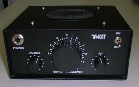
Much more minor is the uncommon connector choices for a modern QRP rig. The
antenna uses a rugged SO-239. The headphone jack is quarter inch. These go well
with the 'heavy metal' theme of the solid black painted case. The RCA jacks on
the back for power and the key (this rig does not include a keyer) are not the
best choice but they work (and could be replaced if one wishes).
First Impressions. The kit arrives in an oversized box, which when you open it includes the shrink wrapped metal case and the manual. All parts arrive inside the shrink wrapped metal case. This rig is NOT lightweight as Ten Tec kits feature heavy duty enclosures - and this in no exception. Since I envision this rig being used in the shack and on car-camping outings the weight is no concern and the ruggedness appreciated. Still, the rig is a reasonably sized small box that is actually a bit oversized given the small PC board. Upon opening the shrink wrap one finds lots and lots of parts to be stuffed upon a small pc board.
Extra Effort Taken. Seeing that there are six identical crystals in the kit, and that four of these are used in the receiver's IF filter - I decided why not match the closest four crystals. I did this by building a simple one transistor oscillator "dead bug" style - with alligator clips for attaching the crystal. First I tried measuring each by tuning and recording the frequency. Given a receiver with a 500 Hz filter - and trying to measure to < 100 Hz accuracy proved to be ineffective. But here is a technique that works: tune the receiver to where the crystals seem to be centered - a compare each of crystals to a selected "reference" crystal. Using this technique, I was able to pick the four crystals that were closest in pitch. The difference in pitch between these four was observed to be less than 100 Hz - good for trying to achieve a nominal 500 Hz filter. One was clearly off-pitch by at least 200-300 Hz and one was slightly off pitch compared to the other four. I feel this effort is worth it and very do-able without a frequency counter - and I am pleased with the results - a very sharp CW filter rivaling my Kenwood rig! Assembly Notes. Overall the assembly procedure is pretty straight forward. The first stage involves building the T/R circuit and ends with a test. Here I put the power leads in backwards, and looking at the reviews posted at eHam others made the same mistake. Some of them report component damage; I was fortunate to be using a supply with current limiting that may have saved me! It turned out, this was the only error I made it kit assembly. The VFO assembly involves a torroid that determines the operating range of the transceiver by manually adjusting the wire spacing. This is kind of cumbersome but if I were homebrewing I would likely be doing the same thing. After lots of effort to "get it right" I used hot glue to attach this torroid to the PC board. I did another preliminary test on the receiver - this is done before the final audio stage is assembled. I was away from home using just a piece of wire for the antenna - so I found this test to be pretty much a waste of time. Upon assembling the complete receiver - I had the "music" of many nice CW signals across the band and verified the nice response of the crystal filter. Many have reported a little difficulty when the final installed to the heat sink. I was patient on this step, and careful to make measurements several times during assembly to verify the final transistor flange was not shorted to the heatsink. Everything went together nicely (I can't say this about everything I have built...) and now I enjoy a home constructed 40m transceiver that is a joy to operate.
Modifications. These words ended my first posting to the web. I wonder how long before I discovered
the raspy sidetone? The primary cause of this malady is the poor layout - too little
space was allowed for the PA circuit. In my own experimental work I determined the
main factor for my rig is coupling energy into T1, a bifilar transformer that biases
the PA. Its composition is not identified in the TT1340 manual but it appears to be
feritte. My explanation is that its higher permeability makes it more sensitive to
stray fields from the transmit low pass filter inductors. In my case I was able to
position these inductors as far away as possible from T1, and oriented to minimize
their interaction. Note I have T1 flat against the board and pushed away from the
low pass filter inductors. These inductors are pushed away from from T1 and oriented so they are not side-by-side. Yes I have one inductor even touching the PA heat sink with no issues. Important to glue down these inductors because they can move - I learned this
the hard way. The picture below shows the orientation used for these components.
To further improve stability at the suggestion of N5ESE I also modified the bias to
the input of the PA. Bias resistor R43 was lifted and a choke is placed in series with it. I used an encapuslated 10 uH inductor from the junkbox. At the end of the inductor where it connector to the 12 volt supply a 0.1 uF bypass capacitor to ground is added. I tried using this without the original bias resistor in series with the inductor, but I got better stability with the resistor also in the circuit.
The only other modification made to the TT1340 is the audio 'hiss' reduction mod suggested also by N5ESE (it is a resistor and capacitor installed across the audio amplifier - see his website for details).
 A nice superhet receiver
VFO with about 70 kHz tuning range
Respectable 3-4 watt output power
Receiver Incremental Tuning (RIT)
Crystal filter
Generous audio from that top mounted speaker
Substantial enclosure
