Well, the gang at Norcal have come up with another one! Later this year, they plan to introduce a 10 meter rig using surface mount parts. To get us all warmed up for it, they came up with this little 40 meter job so we can get some practice with the tiny parts. This is called the SMK-1 and you can see the whole story by clicking on the link. Also see Red Hot Radio's page.
Basically, the rig is a Tuna-Tin 2 plus MRX on a single board but built with surface mount parts. Thankfully, they used the large, 1206 parts where there was a choice. Just today I took a peek inside my new 2800H, and they used some 1206's where they needed the power capability - they are absolutely huge compared to the 0403's.
Wow - building this radio is a whole new experience. The parts are really tiny, and my soldering iron is truly huge. It took quite a bit of care to get those tiny parts soldered down where they belonged, but in the end it worked fine with no problems.
I used 2 different techniques, described in various other pages. For the parts with 2 connections on opposite ends, I basically pushed the part into a pool of molten solder on one pad. With the part held in place I could now (more or less) easily solder the other end. For multilegged parts, I used a surface mount holder-downer built from a dowel, coathanger and fishing weight following the lead of many others who built similar devices. With the part held in place both hands are free for soldering.
In spite of the huge size of all my soldering iron tips, only the SOT-8's required that I resort to extending the tip with a piece of wire. (Why on earth does a 78L06 come in an 8 legged package?) I kept my iron at the recommended 700 degrees F, but I had the feeling it was too warm. Also, I used silver solder as suggested.
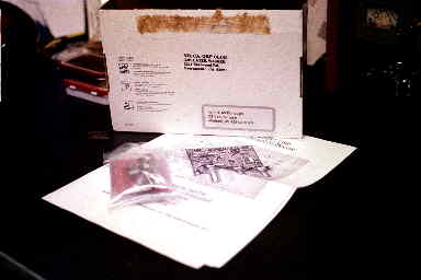 |
The kit comes in the now standard QRP Priority Express box. Inside is a manual and a single, small bag of parts. |
|
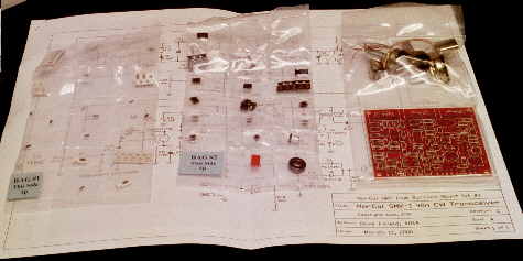
Opening up the parts bag one finds 3 smaller bags, each with individual heat sealed compartments. The bag on the right contains 2 compartments, one for the controls and larger parts and the second for the circuit board. The remaining 2 bags, labeled "Bag 1" and "Bag 2" each have 21 small compartments, each of which contains a small number of parts. |
 |
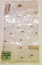 |
Here is a picture of Bag #1. At the upper left is a cardboard tape contianing 13 0.1uf capacitors. The other compartments contain a smaller number of parts, but each compartment contains parts of the same type. |
|
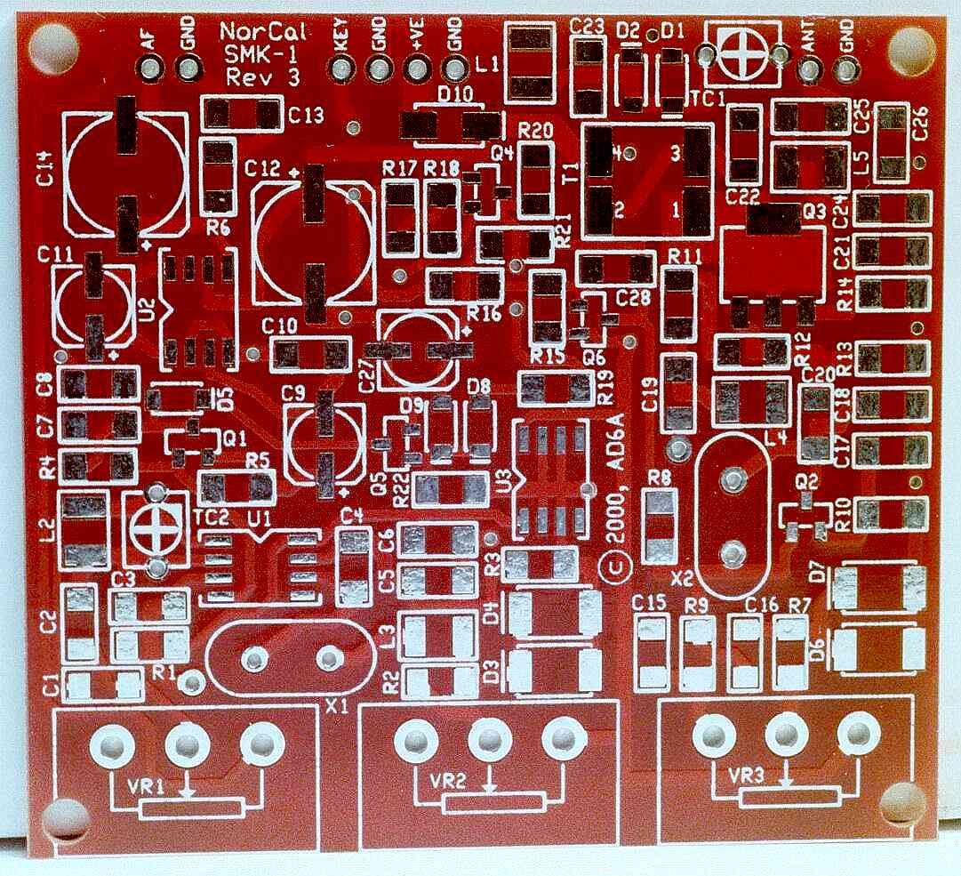
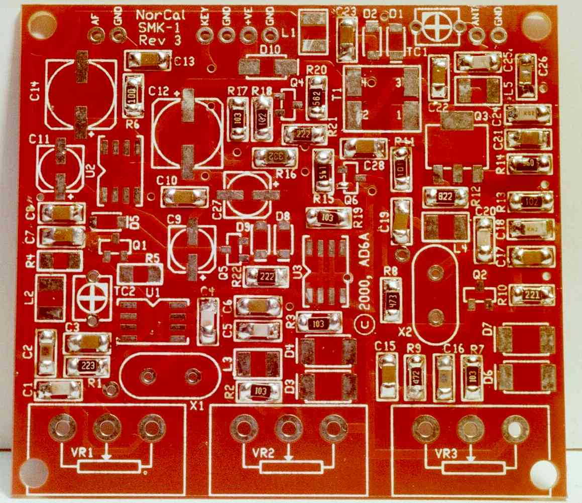
Here is the little circuit board. Note the really nice job of solder masking which seems to be a hallmark of the Norcal kits and is an absolute necessity for this little rascal. Click on the image to get a better view (157K) |
 |
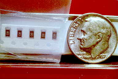 |
Here is a close look at some of the resistors. When I first looked at the bags, I thought these were among the smaller parts. When I got to bag 2 I discovered that some of the transistors, hidden in black, plastic tape, were way smaller. Take a look at the size og Q6 (center of the board) in the last image. |
|
Construction proceeds from left to right, top to bottom, through the bags in sequence. Here is the view at the end of bag #1 ... most of the resistors and caps are mounted, but none of the active devices. Click on the image for a closer view (jpg, 125K) |
 |
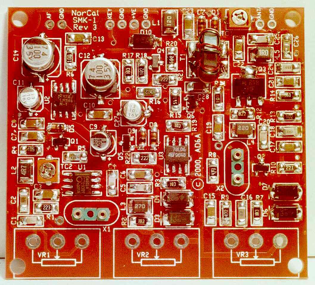 |
At the end of bag 2, all of the surface mount parts are mounted, as well as 5 of the 8 through-hole parts. The machine pins for the crystals are my addition. Click on the image for a closer view (jpg, 124K) |
|
Here is the completed kit. The controls, from top to bottom, are transmitter frequency, receiver frequency, and RF gain. The frequency controls only allow for a small shift, with the receiver range being somewhat wider than the transmitter. Click on the image for a closer view (jpg, 181K) |
 |