The 706 can be a fairly ugly radio if you don't want to shell out mucho bux for an Icom automatic antenna tuner. Although a manual tuner will work, getting the radio to put out a steady signal so you can tune is a bit of a pain.
The radio does have a tune button to cause it to put out a 10 watt carrier, but the button won't work unless it recognizes an Icom tuner plugged into the back. Chris, G4FZN, came up with a nice little circuit to solve this problem.
706 Tune Control Schematic
In building this, I decided to use Manhattan style construction, a la K8IQY. With Chris' schematic in hand, the first step is laying out the parts and the necessary pads.
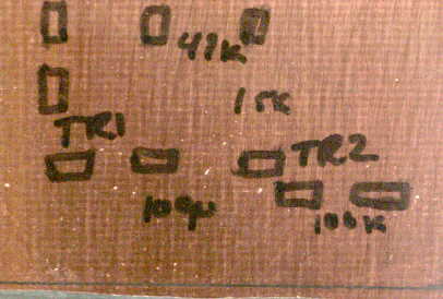
706 Tune Control Parts Layout
I did this in a graphics editor that works in layers so it was a simple matter to print out only the pads to trace on to the copperclad.
706 Tune Control Pad Placement
The next step is to trace the pad placement onto a piece of copperclad. I simply laid a printout of the pads over the board then poked at each corner of a pad with a permanent marker, allowing the ink to bleed through the paper. Then I could connect the dots to get the pad outlines.
Circuit board marked up ready for gluing pads
Now I can glue the pads (cut from copperclad with a Radio Shack nibbler) on to the circuit board and tin them.
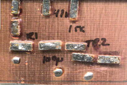
Circuit board with pads ready for parts
Well, after attaching the parts and plugging the little board into the back of the radio it works like a champ. Pressing the tune button causes the radio to emit 10 watts for about 10 seconds - just about enough time to twiddle the knobs on my tuner!
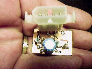
Finished Board