There are now several good dual-
band (144/430MHz) antennas available.
Unfortunately, many of the dualband
rigs which are available have
separate antenna input sockets for
each band. How do you cope with the
problem of getting one plug into two
sockets? The answer is a simple bit of
circuitry called a diplexer. This is a
device which sorts out the various
frequencies and routes them to the
appropriate rig. They are available
commercially at a rather nasty price
but those that I have measured, whilst
safe to use, do not show up any too well
on separation and also tend to have an
unacceptable loss when placed in
circuit.
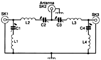
The Circuit
The circuit of a home-made diplexer
which is well within the construction
capabilities of the newcomer to homebrewing
is shown in Fig. 1.
It consists
of three coaxial sockets and four series-
resonant circuits. Hopefully you will
remember that a serics-resonant circuit
has a very low impedance at
resonance and a high impedance off
resonance. How does the circuit work?
Consider a 144MHz (2m) signal
coming in on the antenna socket SK2.
The tuned circuit L2/C2 is resonant at
144MHz and. having a low impedance,
passes the signal to the 2m output SK1.
The tuned circuit L3/C3. being resonant
at 433MHz, exhibits a high
impedance at 2m and so stops the
144MHz signal from reaching the
70cm output socket SK3. On 433MHz
the opposite action takes place.
More Protection
The action already described will do
a fair job but it can be improved upon.
The tuned circuit L1/C1 which is connected
from the 2m output to earth is
series resonant at 433MHz and so any
signal at that frequency which manages
to find its way through L2/C2 is shorted
to earth. As it has a high impedance
off resonance. L1/C1 has no effect on
the 144MHz signals. The tuned circuit
L4/C4 is series resonant at 144MHz
and removes any leakage at that frequency
which reaches the 70cm output
socket.
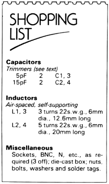
Specification
How well does the circuit do its job?
Looking first of all at the insertion or
through loss. this was measured at less
than 0.1dB on 144MHz, and was
slightly higher at 0.17dB on 433MHz.
When you consider that you need a loss
of 3dB to lose one S-point of signal
strength, these losses can be disregarded.
The blocking of 144MHz at the
70cm output, and of 433MHz at the
2m output was greater than 60dB. This
means an unwanted output of 1
microwatt for every 1 watt of power
applied, which is more than
satisfactory.
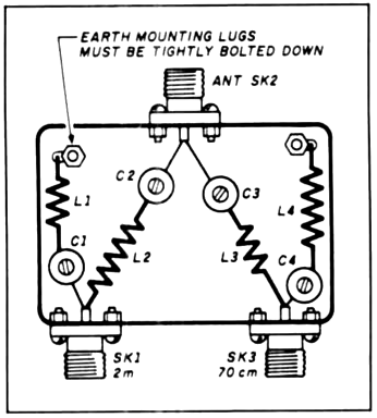
Construction
The unit can be built in a small diecast
box, and a suitable layout is shown
in Fig. 2.
Trimmer capacitor types
required will depend on the transmitter
powers to be used. Ceramic piston and
compression types are suitable for low
powers, for higher powers airspaced
trimmers (e.g. Jackson C804 series) will
be necessary.-Ed.
Tuning the unit is simple. First
connect the rigs to the correct output
sockets. Until all the following steps are
completed DO NOT TRANSMIT.
Tune the 144MHz rig to a strong
signal and adjust C2 for the highest S-
meter reading. Tune the 433MHz rig
to a strong signal and adjust C3 for the
best S-meter reading.
Now connect the 144MHz rig to the
70cm output on the diplexer and the
433MHz rig to the 2m output. Tune to
a strong 144MHz signal and adjust C4
for minimum S-meter reading. Tune to
a strong 433MHz signal and adjust C1
for minimum S-meter reading. For
safety, run through all the above steps a
second time then reconnect the rigs to
the correct outputs and the job is
completed.
Adjustments can be made using a Micro VNA.
Reference: Practical Wireless, October 1988, page 22 Ham Radio, September 1989, pages 30 and 31
A 2m/70 cm diplexer with a difference
Frank, ZS6TMV / PA3GMP
Based upon a design by Henk, PA0HVA,
published in Elektron, June, 1994
Note that this design would need to be scaled to the US 2m and 70cm bands.
Diplexers - filters intended to
split and combine signals
on different frequency
bands - generally use conventional
L/C networks: a low pass
filter for the 2 m band and a high
pass filter for the 70 cm band, each
consisting of several coils and capacitors
with a cut-off frequency
around 250 MHz or so. The maximum
RF power that the diplexer can
handle depends mainly on the
breakdown voltage of the capacitors.
Your average ceramic capacitor is
rated at 50 V, so your diplexer will
start to burn out at about 50 W.
High voltage (trimmer) capacitors
can be hard to find, and can be
bulky enough to interfere with optimal
filter construction, thereby increasing
the diplexer's insertion loss
and reducing its suppression.
The diplexer described below
takes a different approach to the
task at hand. It is based upon two
quarter wave coax stubs, each com-
bined with a simple filter that only
requires one trimmer capacitor each.
At resonance, the filter grounds one
end of the stub, this results in a high impedance for that frequency at the
other end of the stub.
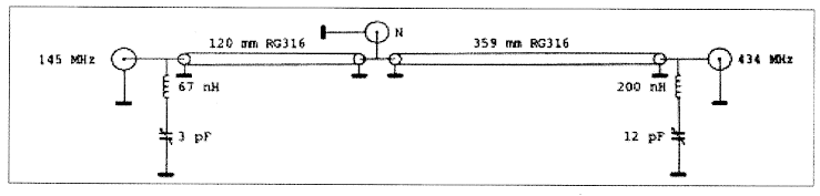
For example, a 145 MHz signal
connected to the left hand side (2 m)
terminal will traverse the left hand
side coaxial line to the common terminal,
virtually without experiencing
any loss. The left hand side filter
resonates at 434 MHz, and will
therefore not affect the 145 MHz
signal. The right hand side L/C circuit
is resonant at 145 MHz, though,
and the right hand side end of the
right hand side coaxial stub will
therefore be grounded. The right
hand side coax stub will present a
very high impedance to the common
terminal as a result, thereby stopping
the 145 MHz signal from continuing into the right hand side coaxial
line. The same (in the opposite
direction) applies to signals at 434
MHz.
This results in a diplexer that
can be used to connect two antenna's
to a dual band transceiver,
or two single band transceivers to a
dual band antenna.
Construction is simple, but must
be done accurately, and it is important
to use the proper components.
The coaxial cable should ideally be
RG-316, which is a very thin, 50
ohm coax with Teflon insulation and
dielectric. Its velocity factor is 0.695,
which means that a quarter wave
stub for 145 MHz will be 359 mm,
and 120 mm for 434 MHz. The main
advantage of RG-316 over RG-174
(another thin but non--Teflon 50
ohms coax) is that good, short soldered
connections can easily be
made to the braiding, which is essential
for the filter's performance.
Other coax could be used as well,
but thicker cable (such as RG-58)
makes it more difficult to solder the
cable and fit it in, while non-Teflon
varieties are much more difficult to
solder close to the dielectric. Some
alternatives are RG-142 (more or
less a Teflon variety of RG-58), RG-174
(thin, non-Teflon, with a higher
insertion loss than RG-317) or, if you
really have no other option, RG-58.
If you use anything else than RG-316,
though, YOU MUST OBTAIN
THE EXACT VELOCITY FACTOR
for the cable you use from the
manufacturer's data sheet. Do not
guess, do not use rule of thumb, do
not use the specs for the same type
of cable from another manufacturer.
Then recalculate the length of the
stubs to the millimeter.
The trimmer capacitors should
be of the best quality you can get.
Ceramic types are preferable because
they can take higher voltages -
(and therefore more RF power)
while tubular capacitors are preferred
from a construction standpoint
because they can be mounted directly
into the chassis of the box.
(Hint: that old valve radio stuff that
you passed up on, the last time you
were at a ham radio flea market
generally has the caps you need!) I
used tubular trimmer capacitors of 6
and 12 pF for 70 cm and 2 m, respectively.
It does not really matter
if the caps you use are a few pF
over the 'desired' capacity - that is
why they call them "variable." The
ones I used are rated at well over
200 V, which means that the diplexer
allows for
more power than my
ham radio license.
The coils are
made out of 1.5 mm
solid copper wire. I
used silver plated
wire, but you can
also use enamelled
copper wire without
any appreciable loss
of filter quality. The
coil for 2 m (200 nH)
consists of 7 windings
on the smooth
end of a 9 mm drill bit, stretched until
the length of the coil is 20 mm.
The one for 70 cm (67 nH) has 5
windings on a 6 mm drill bit,
stretched until the coil is 10 mm
long.
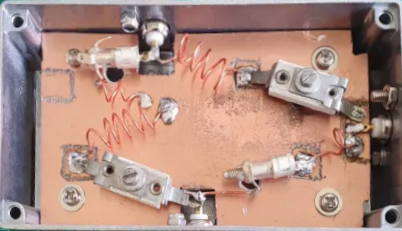
The shield. of the coax is soldered
directly to the lugs, while the
core is clipped off at a length of 5
mm or so, and connected to the center
pin of the terminals. See the
photo for construction details.
Note that the length of the wire
between coax and center pin is not
counted as part of the length of the
stub, i.e. the 70 cm stub should be
120 mm along the length of the
shield, plus 5 mm of bare center
lead at each end.
Alignment is simple. Apply a
145 MHz signal to the common terminal.
Connect a power meter
(SWR meter, directional watt meter
or RF volt meter) to the 434 MHz
terminal, and a 50 ohms dummy
load to the 2 m terminal. Adjust the
145 MHz variable capacitor until the
RF signal at the 434 MHz terminal
dips to zero. Then move the power
meter to the 2 m terminal and the
dummy load to the 70 cm terminal,
apply a 434 MHz signal to the common
terminal, and adjust the 434
MHz variable capacitor until the RF
signal at the 145 MHz terminal dips
to zero. (Don't get confused here:
you should connect the Wattmeter to
the 2 m terminal when adjusting the
70 cm filter using a signal at 434
MHz, and vice versa!) I used two
separate Wattmeters, but this is by
no means necessary.
It is easier to use a Micro VNA to set the trimmers.
Measured performance
The suppression of the diplexer
is especially important when you use
the diplexer to connect one dual
band antenna to two single band
transceivers. A single band radio
can be expected to have an input
filter providing at least 20 to 30 dB of
suppression of out- of- band signals.
That brings the minimum total suppression
to 45-55 dB or so, which
means that if you use two single
band transceivers and one dual
band antenna, 100 W at 145 MHz
will result in only a few mW into the
first stage of your 70 cm transceiver,
and vice versa. Both transceivers
will be able to handle this with ease.
For the US Amateur Bands - the 2m stub for 146 MHz would be 357 mm, the 70cm stub for 446 MHz would be 117 mm.
Reference: Radio ZS, May-June 2009, pages 15, 16, and 20