 The first power supply that was converted to this design was a 1960s vintage IBM SMS Power Supply.
The first attempt to repair and use was to replace the germanium SMS card preregulator and overvoltage cards with a discrete silicon transistor design.
The second mod was to use a LM309 boot strap circuit to replace the descrete transistor preregulator.
The third mod is as below.
The first power supply that was converted to this design was a 1960s vintage IBM SMS Power Supply.
The first attempt to repair and use was to replace the germanium SMS card preregulator and overvoltage cards with a discrete silicon transistor design.
The second mod was to use a LM309 boot strap circuit to replace the descrete transistor preregulator.
The third mod is as below.
Why "Upside Down"? Using a negative regulator, cheap NPN pass transistors, and regulating the negative side of the supply actually has some advantages.
The foremost is that the heat sink and collector of the pass transistors can be at the negative terminal output potential (ie. Ground). No insulation is necessary on either the transistors or heatsink. Apply some thermal compund and bolt the transistors directly to the heat sink.
The use of the 3-terminal negative regulator greatly simplifies the regulator curcuit over that of a 723 based design
Circuit Description and Design
Unfortunately, the discussion of the current boost circuit in AN-103 has several problems due to over simplification.
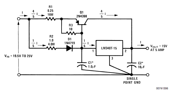
- The pass transistor base current cannot be ignored especially when several pass transistors are paralleled. The voltage drops across R1 and R2 in Figure 6 are NOT equal.
- R3 exists solely to force the pass transistor ON at low currents. Without R3, the pass transistors are off until the base voltage approaches 0.7V.
- Without R3, D1 is unneccessary.
- Typical 2N3055 transistors in my junk box have DC current gain of 5 - 10 at 5A of collector current. The DC current gain from 0 to 5A of collector current is very non-linear.
- At full load of 25A, regulator current was measured at 1.2A; base current into 4 2N3055s was about 2A. 2N3055s were just about saturated.
Schematic

Do not remove the emitter resistors. The 0.1 ohm emitter resistors help compensate for DC gain variations among devices. The base currents will not be equal but collector currents will be nearly equal.
For 2N3771 or similar higher power transistors the emitter resistor can be lowered to 0.05 ohm. With 2N3771s most of the voltage drop across the 2 ohm resistor is from regulator current.
No foldback current limiting is used or desired. Power supply foldback current limiting often is the cause of transmitter peak distortion and IMD. A cheap fuse works just as well.
Several power supplies based on this design have been in regular use since the early 1980s. Only failure was lightning damaged the 7912 and one 2N3055. These supplies were surplus/bad from the early 1960s. The original 1960s Germanium pass transistors were removed and newer 1970s Silicon transistors added. The old regulator was removed and replaced with this simple design. The Aluminum heat sink is 6 inches wide by 14 inches long. No additional cooling has been needed.
Alternate Input Circuit for Bridge Rectifiers

- Reference: