MFJ-949B Deluxe Versa Tuner II
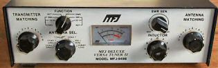
The MFJ-949B is designed to match virtually any transmitter to almost any antenna, including dipoles, inverted vees, verticals, mobile whips, beams, random wires, and others fed by coax line, balanced lines, or a single wire. A 1:4 voltage balun is built in for connection to balanced lines. An antenna selector switch provides versatile antenna selection. A 50 ohm dummy load is built in for easy transmitter tuning. The MFJ-949B wilil handle up to 300 watts of RF output power from the transmitter from 160 through 10 meters. The SWR, forward power and reflected power meter provide measurement for SWR, forward and reflected power in watts.
The meter on the MFJ-949B can be used with the tuner or by itself. To use the meter without the tuner set the ANTENNA SEL. to Coax 1 Direct or Coax 2 Direct.
To read forward transmitter RF output power, sumplty turn the meter FUNCTION switch to 30 or 300 on FWD. To read reflected power simply turn the FUNCTION switch to 30 or 300 on REF. The meter will read maximum of 30 watts on 30 and 300 watts on 300.
To read SWR, turn the FUNCTION switch to SET and adjust the SWR SEN. control for full meter scale deflection while transmitting, then turn the FUNCTION switch to SWR to read SWR. In order to have an accurate SWR reading, the SWR SEN. control must be set for full scale deflection whenever power level changes. Maximum sensitivity for the meter is approximately 5 watts. For power less than 5 watts, the SWR will not read accurately, however, minimum reading in the SWR position is minimum SWR.
The ANTENNA SEL. switch allows selecting two coax antennas either direct or thru the tuner, a balanced line antenna or wire antenna or a built in 50 ohm dummy load. The 50 ohm dummy load is rated at 200 watts.
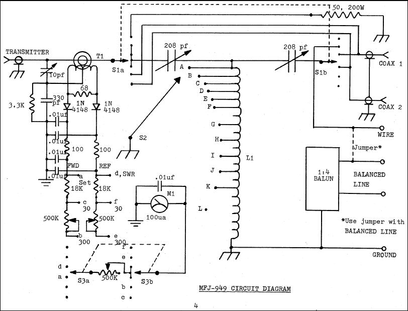
In any conventional "T" network tuner, maximum power handling and the smoothest tuning occurs when the capacitance in the network is as large as possible. In this tuner the TRANSMITTER and ANTENNA controls have maximum capacitance at position 0 (fully meshed), and minimum capacitance at position 6 (fully open). Be sure to use the highest possible capacitance for each band. This will provide the smoothest tuning, highest efficiency, and greatest power handling capability. The chart in the tuning instructions shows typical capacitor settings that can be used for each amateur band.
The INDUCTOR switch in the MFJ-949B has maximum inductance at position L and minimum inductance at position A. Less inductance is required as frequency is increased. If too little inductance is used, the tuner may not match the load properly. If too much inductance is used, the tuner will be "touchy" and power handling will be compromised. The chart in the tuning instructions shows typical INDUCTOR switch settings for each amateur band.
Most modern solid state transceivers do not require adjustments. If the transceiver has a built in antenna tuner, be sure it is turned off or disabled.
After properly preparing the transmitter, set the ANTENNA SEL. switch to the the desired antenna. Adjust the tuner as described below to obtain the best SWR. DO NOT change the transmitter's tuning (plate) or loading (antenna) controls until after the tuner has been fully adjusted. The transmitter can be "touched up" (if necessary) after the MFJ-949B is fully tuned.
When using the MFJ-949B in receive only applications, adjust the MFJ-949B for the highest "S" meter or signal level. The Tuning Chart can be used as a starting reference.
To use the MFJ-949B for transmitting, follow the steps below:
| Freq. MHz | Transmitter | Antenna | Inductor |
|---|---|---|---|
| 1.8 | 1 | 1 | L |
| 1.9 | 1 | 1 | L |
| 2.0 | 1 | 1 | L |
| 3.6 | 2 | 2 | J |
| 3.9 | 2 | 2 | I |
| 7.15 | 2.5 | 2.5 | H |
| 10.15 | 3 | 3 | G |
| 14.15 | 3.5 | 3.5 | E |
| 18.2 | 4 | 4 | D |
| 21.1 | 4.5 | 4.5 | C |
| 24.9 | 5 | 5 | B |
| 28.5 | 6 | 6 | A |
Your DELUXE VERSA TUNER II will reduce the SWR of most antenna systems to 1:1. In a few rare cases, a perfect 1:1 SWR may not be obtainable. If this is the case, the length of the antenna or the feedline can be changed slightly until a low SWR can be obtained. See the antenna hints section.
If this tuner fails to tune, please double check all connections and follow the tuning procedures again. Be sure you are using enough inductance (a higher INDUCTOR switch setting, higher alphabet) and have the capacitors open far enough (a higher front panel number).
If this tuner arcs at the rated power levels, please double check all connections and follow the tuning procedures again. Be sure you are using the largest amount of capacitance and lowest amount of inductance (lowest INDUCTOR switch setting (lower alphabet), TRANSMITTER and ANTENNA numerical setting possible) that allows the load to be matched on the operating frequency.
If you are still unsuccessful, but the tuner does adjust and operate when switched to the DUMMY LOAD position or another antenna, please read the Antenna Hints text.
To minimize RFI, single wire feedlines (such as used with Windom or longwire antennas) should be kept away from other wiring. Radiation will be minimized if the single wire feeder runs parallel and reasonably close to the wire that connects the tuner to the outdoor ground. The antenna feed wire should be adequately insulated to prevent arcing or accidental contact.
For safety, please use both dc and RF grounds. It is particularly important to have a good RF ground while using a single wire feeder. When using a single wire feeder, the tuner needs something to "push" against in order to force current into a single wire feedline. If a good RF ground is not available, RF will usually find it's way back into the power line (RFI), transmitter audio circuits (RF feedback), or the operator (RF burns).
Water pipes and ground rods provide good dc and ac safety grounds, but they are often inadequate for RF grounding because they are single conductors. RF grounds work much better when "spread out" over a large area with multiple connections directly to the equipment ground point. Water pipes, heating ducts, and fences may work (especially if they are all connected together with jumper wires), but the best RF grounds are radial systems or multi-wire counterpoises that provide large low resistance surfaces for RF energy. Ground rods by themselves are almost useless for dependable RF grounding.
RF and lightning travels on the surface of conductors. Braided or woven conductors have high surface resistance to lightning and RF. Ground leads for RF and lightning should have wide smooth surfaces. Avoid the use of woven or braided conductors in RF and lightning grounds unless the lead needs to be flexible.
For the best performance, an end-fed longwire wire antenna should be at least one quarter wavelength long at the operating frequency. Horizontal antennas should be at least a half wave long and high and clear of surrounding objects. While good RF grounds help the signal in almost any transmitting installation, it is extremely important to have good RF grounds with long wire or other Marconi antennas.
Most matching problems occur when the antenna system presents an extremely high impedance to the tuner. When the antenna impedance is much lower than the feedline impedance, an odd quarter-wavelength feedline converts the low antenna impedance to a very high impedance at the tuner. A similar problem occurs if the antenna has an extremely high impedance and the transmission line is a multiple of a half-wavelength. The half-wavelength line repeats the very high antenna impedance at the tuner. Incorrect feedline and antenna lengths can make an antenna system very difficult or impossible to tune.
This problem often occurs on 80 meters if an odd quarter-wave (60 to 70 foot) open wire line is used to feed a half-wave (100 to 140 foot) dipole. The odd quarter-wave line transforms the dipole's low impedance to over three thousand ohms at the tuner. This is because the mismatched feedline is an odd multiple of 1/4 wavelength long. The line inverts (or teeter-totters) the antenna impedance.
A problem also occurs on 40 meters with this antenna example. The feedline is now a multiple of a half-wave (60 to 70 foot) and connects to a full-wave high impedance antenna (100 to 140 foot). The half-wave line repeats the high antenna impedance at the tuner. The antenna system looks like several thousand ohms at the tuner on 40 meters.
The following suggestions will reduce the difficulty in matching an antenna with a tuner:
If you have any problem with this unit first check the appropriate section of this manual. If the manual does not reference your problem or your problem is not solved by reading the manual, you may call MFJ Technical Service at 662-323-0549 or the MFJ Factory at 662-323-5869. You will be best helped if you have your unit, manual and all information on your station handy so you can answer any questions the technicians may ask.
You can also send questions by mail to MFJ Enterprises, Inc., 300 Industrial Park Road, Starkville, MS 39759; by Facsimile (FAX) to 662-323-6551; or by email to [email protected]. Send a complete description of your problem, an explanation of exactly how you are using your unit, and a complete description of your station.
Original manual © MFJ Enterprises, Inc.