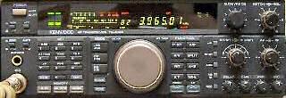
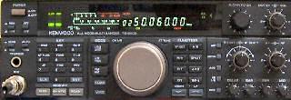
HELP! I Just Got a TS-450/690
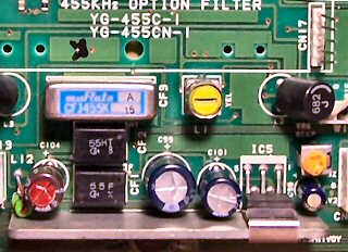
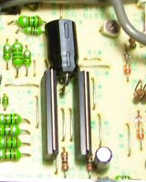
C123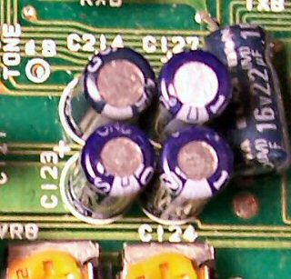 |
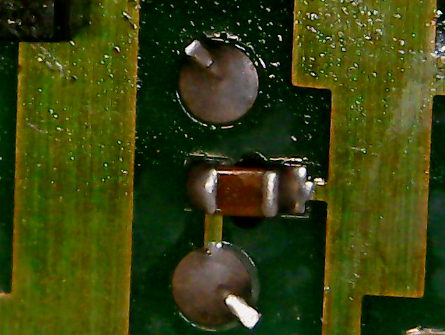
C123 + new 100 ohm resistor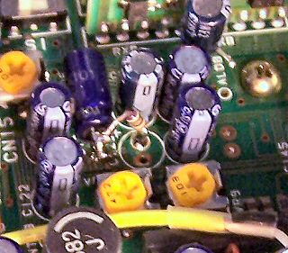
|
new 6.8K ohm resistor across R148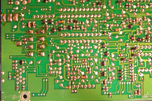 | |
6.8K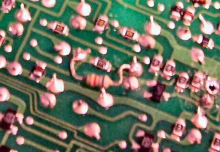 Optical illusion, the resistor lead clears that adjacent pad. |
Schematic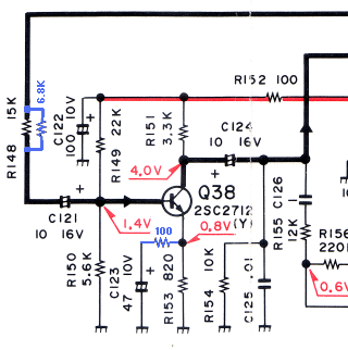 |
| uv | 0.2 | 0.4 | 0.8 | 1.6 | 3.3 | 6.3 | 12.6 | 25.1 | 50 | 160 | 500 | 1600 | 5000 | 15000 | 50000 |
|---|---|---|---|---|---|---|---|---|---|---|---|---|---|---|---|
| S | 1 | 2 | 3 | 4 | 5 | 6 | 7 | 8 | 9 | 10 over | 20 over | 30 over | 40 over | 50 over | 60 over |
.jpg)