A Patch for the TS-120S
When I bought a Kenwood TS-120S and sold my Drake TR-4C, it cost my station phonepatch capability. There's just no graceful way of mating the existing patch with the Kenwood's input and output accesses . That brought on the challenge of second-guessing the Japanese engineers. Sometimes that's easy; often it's not. There seems to be an unwritten law (or is it written?) that all equipment must be designed to make customer modifications difficult.
A bit of study of the schematic wiring diagram for the TS-120S reveaed an unused terminal (#7) on the remote connector. More study revealed that audio signal and send-receive functions were available at the remote connector. Ah, now if one had microphone input also available ... Could it be just a matter of piping a wee bit of audio to the mic input jack from that unused (#7) terminal? It looked feasible on paper, but it pays never to leap too precipitately to conclusions. So the next step involved a bit of exploration of the innards.
If you've never uncovered your TS-120S, a word or two of advice might be of worth. Take the top cover off first, taking care not to disturb the four screws that hold the internal speaker in place. It's not necessary to remove the top totally; just loosen it and slightly move it from place. Now you can flip the set over on its top side without endangering the three top controls and without having to worry about the lead to the speaker.
With the top loose, the bottom comes off readily. Once it's off, take a look at the back side of the mic connector. One of the four terminals has a single white wire going to it. That's the one you're interested in! And it's the one most easily reached! No doubt the Japanese engineer responsible for this grievous faux pas has been compelled to commit hara-kiri.
But how about the other end? Not to worry! There's a plate mounting a number of jacks, the remote connector among them. This plate comes out with the removal of five screws. Once out, terminal #7 is most easily reached. Ah, breathe a prayer for the soul of the poor engineer!
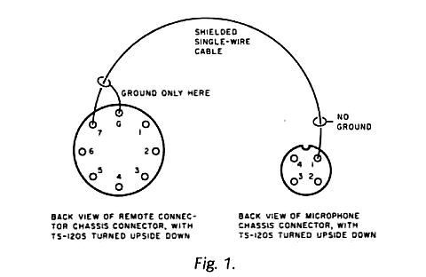
Now, all that remains is to find a single-wire shielded conductor small enough to snake a long the edge of the chassis. There are holes through the compartment shielding to accommodate a small and flexible cable. I suggest you ground the shield of this wire only at one end (I used the terminal #7 end) to avoid ground loops.
The remote connector now provides the following se rvices: ground and #1-audio output, 8 Ohms; ground and #3-send receive control; ground and #7-audio input, high impedance.
You might take a hint from the wiring diagram and put a 100-Ohm resistor in series with that audio output. This will both reduce the signal level (most likely too high for phone lines) and also protect the output transistors from any non-kosher load a phone patch may offer.
The introduction of the capacitance of the short cable accoss the mic circuit has made no detectable difference in the quality of the voice signal from my TS-120S.
Carl C. Drumeller, W5JJ
from 73 Magazine, February 1981, p. 50