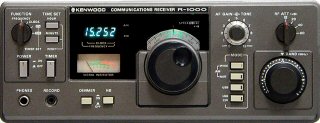
The Kenwood R-1000 is a fine 1980s vintage communications receiver drawing on Kenwoods
experience with similar circuit designs in the TS-120/TS-130/TS-430 Amateur transceivers.
There are a few areas that need to be checked out before use, like the fuse wiring below.
The main tuning is a little fast but should be OK for a general purpose receiver. Some improvements, though, are also needed:
-
A good receiver has an RF gain control. The "tone" control of the R-1000 is of little use.
- AGC action should be selectable independent of mode.
Slow AGC is good for SSB reception. Fast AGC is best for CW.
- The LW band should receive down to at least 100kHz.
- The MW band should have the same sensitivity as the other bands.
- The receiver input muting circuits should be designed for use with transmitters and protect receiver input circuits.
There is plenty of room to provide I and Q outputs as well as install an FM demodulator as future projects.
- Initial Checkout
- Check the fuse wiring.
Many R-1000 were wired wrong. The AC fuse is in the neutral!
- Check power supply.
- Check and replace C209, 4700 uf @ 25 Volts on the power supply board.
- Check for cold solder joints on diodes, resistors, power transistors and regulator ICs.
- On the main RX board, check and replace C186 and C191, both 1000 uf @ 16 Volts.
- Mods
- Change attenuator steps from 20db to 10db. See SB-823.
- Improve MW and LW performance.
- Remove MW/LW RF pad, R161, R163 and replace R162 with a jumper.
- Remove MW/LW IF pad, Q8, R87, R88, R212, and C112.
- Use attenuator as necessary to reduce front-end overload.
- Change LW frequency roll off of input filter (how?).
Parallel 4700 pf across C7 and across C8. Roll off now about 100kHz.
- Improve low frequency audio response.
- Replace C183 with 100 uf @ 16 Volts.
- Remove C158, Q47, R227, R228
- Does changing C183 increase audio IMD?
- Add RF gain control and new AGC circuit.
- Remove C138(?), C139, C140, R119, and R213.
- Use design from TS-120S.
Circuit provides smooth AGC, fast and slow settings.
- Modify tone control to be RF gain control.
- Parts -
- Leave R226 and C217.
- Change R117 to 2.2M ohms.
- Add n-jfet (2n5457, etc.).
-
Add 68K, 100K ohm resistors.
- Add 4.7K ohm from cold side of RF gain to ground.
- Add
50K trim pot from hot side of RF gain to 9 Volt source.
- Apply 9 Volts to top of 68K ohm resistor for slow AGC.
- Rewire DIM push button to be AGC fast/slow selection.
- With RF gain fully clockwise, adjust 50K trimpot to just before the point where the gain decreases.
- Schematic
- Mode switch changes to allow for mode and bandwidth selections. (future)
- New mode table:
| Buttons | Mode | Filter | Demod |
|---|
| (none) | SDR | 12kHz | I/Q |
| AMW | FM | 12kHz | FM |
| AMN | AM | 6kHz | AM |
| AMW+AMN | AM | 12kHz | AM |
| USB | USB | 3kHz | SSB |
| USB+AMN | USB | 6kHz | SSB |
| USB+AMW | USB | 12kHz | SSB |
| USB+AMN+AMW | ? | ? 12kHz | SSB |
| LSB | LSB | 3kHz | SSB |
| LSB+AMN | LSB | 6kHz | SSB |
| LSB+AMW | LSB | 12kHz | SSB |
| LSB+AMN+AMW | ? | ? 12kHz | SSB |
| LSB+USB | LSB | ? CW Filter | SSB |
| LSB+USB+AMN | ? | ? 6kHz | SSB |
| LSB+USB+AMW | ? | ? 12kHz | SSB |
| LSB+USB+AMN+AMW | ? | ? 12kHz | SSB |
- Items in RED, three or more buttons pressed, are probably not useable.
- Items in YELLOW are to be designed. CW filter selection by pressing LSB+USB not easily done.
- Improve antenna switching/selection. (future)
- Improve receiver muting and grounding of antenna inputs when muted. (future)
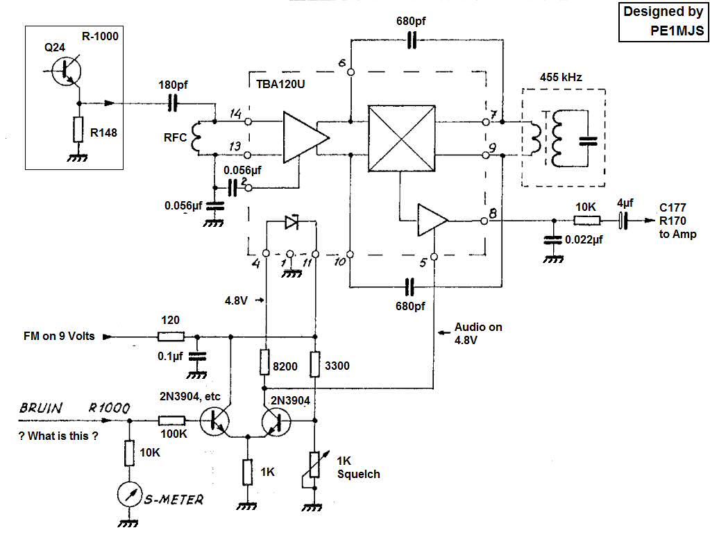
- FM demod (future)
- An FM demodulator designed around a TBA120U has been presented.
Is all of that additional IF gain and limiting really necessary?
- A simpler demodulator based around a PLL could be used instead.
- I and Q outputs for SDR experimentation. (future) Tayloe Detector?