RF-1
RF-1 PICTURE

[Manual]
[Component Locator]
Schematics: [1]  [2]
RF-5
RF-5 PICTURE
VA-1
VA-1 PICTURE

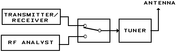
Autek Research RF Analyst

Autek Research is no longer in business.
This document has been created from materials supplied with purchase.

The pocket-sized RF Analyst is designed to check and adjust antennas, feedlines, and RF networks. It includes a microprocessor, A/D converters, and a low-power "transmitter" with 4 digit frequency readout. The RF-1 is continuously variable from 1.2 to 35 MHz in 5 bands. The VA-1 is continuously variable from 0.5 to 32 MHz in 6 bands. The RF-5 goes beyond the frequency range of the RF-1 to cover all remaining ham bands to the 440 MHz band and beyond, plus most frequencies in between. Frequency coverage is 35 to 75 MHz and 138 to 500+ Mhz continuously. This is in three bands of approximately 35-75, 138-290, and 275-500 MHz. The RF-1, RF-5 and VA-1 are truly pocket size. 4.5 x 2.5 x 1.5 in. The battery pack on other units is actually larger than the entire RF Analyst! The RF Analyst runs off a single 9 volt battery in a real battery compartment on the back with a pushoff cover...similar to a TV remote control. A standard 9 V alkaline battery has a life of about 5-10 hours, and can be replaced in seconds. In addition, the unit turns itself off after about 20 minutes if no buttons are pushed. (The auto-off feature can be disabled if desired.)

This illustrated instruction manual discusses many applications in detail, not just instrument operation. Whether you're an expert or novice, this manual will show you many of the things you can do with the unit.

Besides its use by Amateur Radio operators, this unit is in use all over the world at antenna manufacturers, production lines, and laboratories.


ANTENNA MEASUREMENT

When you put up an antenna in the the old days, it could be a real struggle. The only way to tell if it was tuned to the right frequency was to fire up your transmitter and check the SWR over the band you're trying to hit. But if the antenna was not resonant in the band your transmitter covered, about all you might be able to tell is that it is resonant above or below the band. With an Analyst, which goes outside the ham bands, you can tell exactly how much adjustment to make without taking the antenna up or down or running back and forth to your ground-mounted antenna. And it can do so much more! Read on:
ANTENNA MEASUREMNT

SWR MEASUREMENT

As shown above, any Analyst can be used to measure at the far end of the feedline or directly at the antenna. Of course, any type of antenna can be measured--not just verticals. Also, the units can measure balanced line as well as coax, since the unit is so small that it essentially "floats" from ground.

Making SWR plots and determining resonant frequency is the main use for any Analyst. Simply connect as shown above, vary the Analyst frequency and measure SWR.The antenna is resonant at the frequency where SWR is lowest.

If you've never used an Analyst before, you're in for a treat. Previously, the normal procedure for adjusting an antenna was to transmit using your main transmitter and measure SWR. If the SWR was high, it was often difficult to tell what correction to make, since the transmitter is limited to the ham bands.

Using an Analyst you can now tell the resonant frequency exactly and determine exactly how much to shorten or lengthen your antenna after only one measurement. For example, if you're shooting for a 14 Mhz resonance, and the SWR is lowest at 14.56 MHz, this is exactly 4% higher than desired. So you know to lengthen the antenna by exactly 4%. There's no need to keep cutting the antenna and raising and lowering it many times.This is explained in more detail in the instructions.

Furthermore, the frequency of lowest SWR for random length antennas well outside Ham bands can tell you whether to add a coil or capacitor. (For example, maybe you can "tune up" your house gutter!)

The other advantage is that you can take the Analyst outside or up a tower since it's completely self-contained. So you can adjust the antenna on the spot without having to go back to the main transmitter each time you make a change.


TRANSMISSION LINE MEASUREMENT

By measuring an isolated transmission line you can determine:
  1. The loss in the line
  2. The electrical length of the line, e.g. 1/2 wavelength
How lossy is your transmission line? Has weathering or burial ruined it? In the old days,this was very hard to determine. With an Analyst, it is simple:

To measure line loss, simply measure the impedance (Z) of the open or shorted line vs. frequency until you find minimum value. This minimum value reoccurs periodically in frequency. The minimum impedance yields the line loss in dB. For example, if you measure an 8 ohm minimum impedance with 50 ohm line, the loss is about 1.4 dB.( A lossless line would read zero ohms.) Loss in line other than 50 ohms, e.g. 300 ohms, can also be measured. All Analysts are accurate at low impedance with digital readout.The instructions explain this simple procedure further.

The electrical length of the line is also easily found by looking at impedance vs frequency. So it is easy to cut 1/2 wave and 1/4 wave lines.And do it with an accuracy that is better than 1%. Again, more illustrations are in the instructions. Most of these do not appear in any other publications.
TRANSMISSION LINE MEASUREMENT

RESONANT FREQUENCY MEASUREMENT

Changing the Analyst frequency until you find the minimum impedance for the above circuit gives the resonant frequency of the circuit.
RESONANCE MEASUREMENT

TRAP FREQUENCY MEASUREMENT

(It also acts like a "grid-dip" meter, but easier to read, and with digital frequency readout !)

Bonus: Not in Analyst Instructions.

A simpler way to measure the resonant frequency of a trap, or any tuned circuit, is to connect a piece of wire between the Analyst output and the Analyst ground (the ground screw next to the coax connector, or the outside of the coax connector.) The wire can be a few inches to many feet long.(Note:You must disconnect the trap from any antenna to measure its resonant frequency.)

Put the Analyst in the Z mode. You will read a small Z which simply represents the inductance of the wire. Now put the wire near the trap. As you tune the Analyst frequency, Z will increase dramatically at the trap resonant frequency! The frequency of peak Z is the trap resonant frequency.

If the trap has high Q and is large you can probably see the jump in Z with the wire several inches from the coil. For a small coil, you might need to wrap the wire into a small loop at the end and bring it near the coil. No fancy plug-in coils are needed such as a grid-dip meter requires...just a few inches of wire! And the Analyst's digital frequency and Z readout pinpoint the resonant frequency exactly.

The same wire can usually be used over the entire frequency range of the Analyst, so you can also forget about the many plug-in coils that a grid-dip meter requires.
TRAP MEASUREMENT

TUNING AN ANTENNA TUNER WITHOUT TRANSMITTING

If you construct a simple switch as shown above, you can use an Analyst to tune your antenna tuner without transmitting. Simply set the Analyst at the desired frequency and set the tuner for lowest SWR.
TUNING WITHOUT TRANSMITTING

MEASURING COILS AND CAPACITORS

The RF-1 and VA-1 both measure coils and capacitors at the RF frequency of your choice. Simply connect the coil or capacitor across the units coax connector; directly, or using clipleads (supplied.) Both units subtract the stray output capacitance of the connector, etc., so C is usually read directly without any correction required. The VA-1 , which measures the sign of X, will show a negative L if a capacitor is measured. This is often handy since this is the L value which resonates with the capacitor at the measurement frequency. The RF-1 does not measure the sign of X, but will also show the equivalent L value.

Please note that the L and C functions of the RF-1 are only for measuring pure L and C, whereas the VA-1 shows the L or C component of any load (R + jX), including the sign.

COILS ARE MEASURED AT RF FREQUENCY

Please note that one can buy other meters which measure L and C, which are usually intended for TV repair people. These meters usually operate at 1 kHz to 100 kHz and so are essentially useless for RF measurements of coils ! . The inductance of a coil varies considerably at high frequencies because of stray capacitance and other factors.In addition, if the coil is wound on a ferrite core (e.g. toroid), the core material causes the inductance to vary even more with frequency. So, an L/C meter which operates at 1 kHz or 100 kHz will not read RF inductance correctly. In contrast, Analysts can be set to the frequency of interest when measuring L.

MEASURING LINE IMPEDANCE

By connecting a known resistor value to the far end of a transmission line and observing how Z varies with frequency, the line impedance can be determined. This simple procedure is discussed further in the instructions.

MEASURING BALUNS AND OTHER RF TRANSFORMERS

If you have a 1:1 balun, simply connect a small 50 ohm resistor across its output, and verify that Z at the input is also 50 ohms. Similarly, if it is a 1:4 balun, connect 12.5 ohms at the output and verify that 50 ohms is measured at the input. Or, for a 4:1 balun, connect 200 ohms at the output, etc. (Don't expect "perfect" results, and especially expect some degredation at the low and high frequency limits of the balun specs.)

MEASURING "CHOKE" BALUN IMPEDANCE

Bonus: Not in Analyst Instructions.

"Current" baluns are often used to keep current from flowing on the outside of the cable when coaxial cable feeds a balanced antenna such as a dipole or inverted V. Also, vertical groundplanes (verticals that don't use an "earth" ground) should have one, especially if only one or two groundplanes are used, as is becoming more popular. However, compact baluns are easy to burn out at high SWR. So, if weight and size are not a problem, a "choke balun" is often used. This can be made by coiling 4 to 10 turns of the coax feedline in a loop (very simple and cheap), or, similarly, by slipping many ferrite cores over the outside of the coax (not so cheap, but lighter.) See the ARRL Antenna Book for details...sorry, we cannot supply details.

The impedance of the "choke" is easily found by measuring the Z of the coax shield between the input and the output of the "choke." That is, connect the Analyst ground to the coax braid on one side of the "choke," and connect the "hot" end of the Analyst (inside of Analyst coax connector) to the coax braid on the other side of the "choke." You can stick a hairpin through the coax insulation to reach the braid without cutting the coax. Vary frequency, and verify that Z is high over the frequency range of interest. You may measure Z greater than 1000 ohms over part of the range.

ADVANCED USES

The R and X components of the load are often desired. It turns out that R and X can be calculated from SWR and Z, which are read out by the RF-1 and RF-5. The equation to do this is in the instructions. So, if you occasionally need R and X components, this is adequate. Note, however, that this does not yield the sign of X, and the results are not as accurate as using a VA-1. Also, this method does not work above 150 to 200 MHz because of stray inductance and capacitance which can cause large errors in Z.

The VA-1 measures R and X, including the sign of X directly and instantly, and does everything else that the RF-1 does, of course. The VA-1 also shows SWR for lines other than 50 ohms, and shows the R and X components of an antenna in the air. If you're an advanced user, you should consider the VA-1. However, the less-expensive RF-1 is also extremely accurate and adequate for most tasks.

QUESTIONS:

I notice that your Analysts have a coax connector output. Can they also be used to measure on balanced lines such as twinlead and ladder line?

Yes! The Analysts are so small that they essentially float from ground. So just go ahead and hook balanced line to the coax connector. It will measure these just fine. (We could have added two screw terminals in parallel with the coax connector, but this is a waste of space and not necessary.)

What are those round things on the panel next to F, SWR, etc ? Are they LED's ?

No. LED's would drain the battery. All the round things on the panel next to F,SWR,ON/OFF, Band, etc. are pushbutton switches.

What is the reliability of your units? I've had some bad experiences with similar units.

Reliability is considered to be very important. Each unit is thoroughly tested. If any unit, or component, seems to be in any way marginal it is rejected or the component is replaced. The little things are important,too. For example, 9 volt battery connectors are notoriously unreliable. 15 types are stress-tested before settling on the brand used.

Does this mean nobody ever has a problem? Of course not. Some units fail "in the mail" despite tests. Or someone leaves a decal off a unit, or forgets to enclose instructions.