- WARNING
- Installation of this product near power lines is dangerous. For your safety, follow the installation directions.
General Description
The TH3jr antenna was designed for the Ham who has space limitations but still wants top performance on 10, 15 and 20 meters. The TH3jr is constructed of taper-swaged aluminum tubing which offers low wind resistance. It can be rotated with a heavy-duty TV rotator. The light weight is ideal for rooftop or lightweight tower installations. The antenna features super strength stainless steel hardware and a boom-to-mast bracket that will fit masts up to 2 inches in diameter.| Specifications Electrical | |
|---|---|
| Forward Gain | Up to 8 dBi |
| Front-To-Back Ratio | 25 dB |
| VSWR at Resonance | Less than 1.5:1 |
| Nominal Impedance | 50 ohms |
| Power Capability (Transmitter Output) | 600 Watt PEP, 300 Watt AM |
| Lightning Protection | DC ground |
Mechanical | |
| Net Weight | 21 lbs. (11.7 kg) |
| Boom Length | 12 ft. (3.65 m) |
| Longest Element | 27�3" (8.30m) |
| Turning Radius | 14�9" (4.49m) |
| Wind Survival | 80 mph (128 kmph) |
| Accepts Mast | 1 �" to 2" (32 mm to 51mm) |
| Surface Area | 3.35 sq. ft. (0.32 sq. m) |
| Effective Moment* | 310 ft. lb. (53 kg-m) |
| Wind Load at 80 MPH | 87 lbs. (39.4 kg) |
| Hardware | Stainless Steel (except for U-Bolts and some small parts) original hardware was NOT Stainless |
| Suitable Rotators | Hy-Gain AR-40 or CD-45II |
Step-By-Step Assembly
- NOTE:
- When unpacking your antenna, check the inside of all tubing for parts (clamps, insulators, smaller tubing, etc.). To conserve space during packing, these smaller articles are put inside large pieces.
- NOTE:
- The reflector portion of the boom has holes drilled in it for the beta match. Make sure they are on top when you tighten the boom-to mast bracket. See illustration in this manual.
Slip the boom sections into the boom-to-mast bracket until they meet in the middle. Make certain the drilled holes on the reflector end are on top and close to the boom-to-mast bracket, then tighten the bolts securely.
Place a 11/4" caplug on each end of the boom.
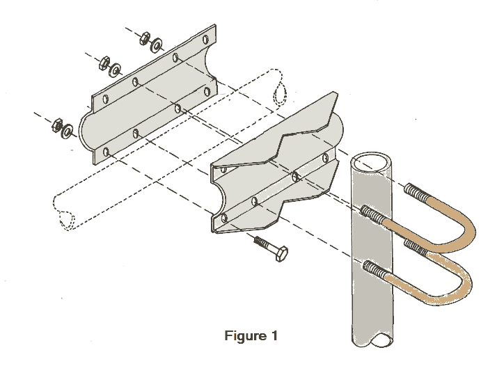
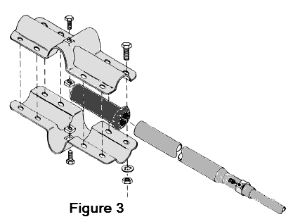
Insert the two U-bolts into the boom-to-mast bracket and start the 5/16" nuts and lockwashers. DO NOT tighten at this time.
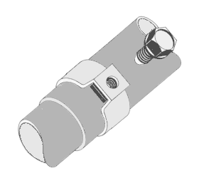
Start at the reflector end (boom section that has the hole drilled in it) and measure approximately 1" from the end of the boom and install the element-to-boom bracket as shown in Figure 2. Only tighten the hardware enough to keep the bracket in place. Final positioning of this element will depend upon placement of the driven element and the dimensions from Figure 4.
Select the Rl sections (7/8" x 72") of tubing and slip one end of each in each side of the bracket and tighten the bracket securely with the exception of the two anchor screws. DO NOT tighten at this time.
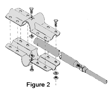
Measure along the boom 65 1/8" from the center of the reflector element-to-boom bracket and install the driven element-to-boom bracket. Select the DE sections and slip the driven element insulators onto one end of the DE1 sections (7/8" x 72").
Slip the insulated end of the DE1 section into the driven element bracket and tighten securely. See Figure 3 for proper installation. DO NOT tighten the anchor screws at this time.
Measure 74" from the center of the driven element bracket to the center of the director and install the director element-to-boom bracket. Select and install the D1 sections (7/8" x 72") by slipping one into each side of the bracket and tighten securely. DO NOT tighten the anchor screws at this time.
Now recheck the measurement and make certain all the elements are aligned evenly.
- NOTE:
- At this time select your mode of transmission - either Phone or Continuous Wave (CW). Refer to the dimensions for your mode of transmission. Use the same mode for all dimensions.
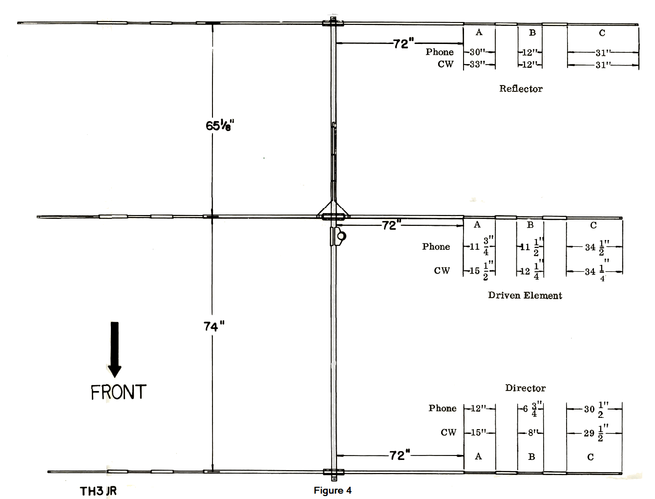
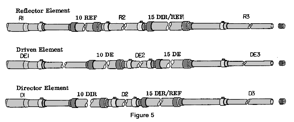
Select the 10-meter reflector trap (marked REF) and a #6 tubing clamp and slip it on the end of Rl. Slip the longest end of the 10-meter trap into the Rl section to the dimensions given for your mode of transmission. Tighten the tubing clamp slightly. See Figure 5.
Select R2 (3/4" x 10 1/2") and slip it onto the 10- meter trap assembly. Slip one #6 tubing clamp on each end of R2. Tighten slightly.
Select the R3 sections (7/16" x 32") and slip it into the 15-meter trap assembly to the dimensions shown for your mode of transmission. Slip on #6 tubing clamp, and tighten slightly.
Place a 7/16" caplug on each end of the element.
- NOTE:
- The remaining elements will be installed in the same manner as above with the exception of using the trap designated for that particular element.
- 10-Meter Traps -
- Director - 10 DIR
- Driven Element - 10 DE
- Reflector - 10 REF
- 15-Meter Traps -
- Director - 15 DIR/REF
- Driven Element - 15 DE
- Reflector - 15 DIR/REF
Select the remaining director tube sections and install as before.
Select the beta match tombstone support insulators as shown in Figure 7.
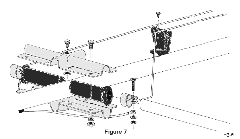
Select the beta shorting strap and install as shown in Figure 7. Tighten all hardware used with the beta match, shorting strap and driven element. Remeasure the dimensions between elements as shown in Figure 4. Tighten all hardware including the anchor screws at this time.
A balun is not required for normal operation of this antenna. However, there are three recommended feedpoint configurations, one of which utilizes the Hy-Gain Model BN-86 balun for increased performance and convenience.
The first feedline configuration involves connection of the coaxial feedline directly to the driven element. The recommended feedline is RG-213/U (such as Belden 8267). Other types of coaxial cable may be used if proper selection and careful assembly are utilized. The feedline should be stripped as shown in Figure 7. Attach solder lugs (not supplied) to the center conductor and shield for easy connection to the driven element. Weatherproof all connections.
The second feedpoint configuration involves construction and installation of a homemade RF choke. The RF choke will prevent RF from flowing on the outside of the coaxial shield. This will block radiation from the coaxial feedline; thereby reducing the risk of TV1 and preventing radiation pattern degradation.
The third feedpoint configuration involves using a 50 ohm 1:1 balun to connect the feedline to the driven element. (Hy-Gain Model BN-86 is recommended.) A balun will act as an RF choke and will balance the flow of current on the driven element, resulting in a symmetrical radiation pattern. A balun will also have a coaxial connector, providing more convenience than a coax splice. Follow the instructions supplied with the balun for connection to the antenna.
- NOTE:
- Use caution when selecting a balun to use
with this antenna. Some baluns are designed for
50-75 ohm impedance and may result in a higher
SWR when used with this antenna. For best
results, use the Hy-Gain BN-86, 50 ohm balun.
The Model BN-86 is available at your local Hy-Gain dealer.
- The original balun used with this model of the TH3jr was Hy-Gain BN-12. If you use the BN-12 and want maximum front-to-back ratio change the "A" dimension on the Driven Element to 10" for Phone and 13 1/2" for CW.
Slip the boom-to-mast clamp over your mast and tighten securely.
This completes your installation.