The ATV-3, ATV-4 and ATV-5 are a series of vertically-polarized, omnidirectional antennas designed to provide complete coverage of the 20-10 meter (ATV-3), 40-10 meter (ATV-4), and 80-10 meter (ATV-5) Amateur Radio bands. WARNING: This antenna is an electrical conductor. Contact with power lines can result in death, or serious injury. The antennas may be used with a transmitter that employs a nominal 50-ohm output, at up to the legal Amateur power limit. When properly assembled and mounted, each vertical will exhibit a relatively low angle of radiation, useful for long distance DX communications or local non-skip signals. Constructed of 6063-TB32 aluminum tubing, each vertical combines a series of telescoping tubing sections with a set of "traps" to produce an efficient, broadband antenna. The use of traps, or parallel-tuned resonant circuits, automatically changes the antenna's effective length, according to the frequency in use. The traps and antenna dimensions have been chosen so that the radiator appears as an electrical 1/4-wavelength on each band. In addition, capacitive loading on the ATV-4 and ATV-5 provides expanded 40-meter coverage, in excess of that exhibited by a similarly short vertical. In conjunction with a highly conductive ground plane or wire radial system, each vertical will present a well-matched load to the coaxial feedline and radio equipment.
Prior to actually beginning the assembly of your Cushcraft vertical, you should spend a few minutes reading this manual, especially the sections describing the mounting configurations and radial/ground systems. With these factors in mind, assembly and installation can be accomplished with a minimum of wasted time and effort.
SPECIFICATIONS
| ATV-3 | ATV-4 | ATV-5 | |
|---|---|---|---|
| Overall Height - CW | 14 ft, 1 in (4.28m) | 20 ft (6.10m) | 28 ft, 4 in (8.64m) |
| Overall Height - Phone | 13 ft, 7 in (4.14m) | 19 ft, 2 in (5.85m) | 24 ft, 9 in (7.55m) |
| Wind Surface Area - CW | 0.92 sq ft (.086 sq m) | 1.26 sq ft (.117 sq m) | 1.49 sq ft (.139 sq ft) |
| Assembled Weight | 5.6 lbs (2.5 kg) | 7.0 lbs (3.2 kg) | 8.5 lbs (3.9 kg) |
| Maximum Mast Diameter | 1-3/4 in (4.5 cm) | 1-3/4 in (4.5 cm) | 1-3/4 in (4.5 cm) |
| Frequency Coverage (MHz) | 28.0 - 29.2 21.0 - 21.5 14.0 - 14.4 |
28.0 - 29.2 21.0 - 21.5 14.0 - 14.4 7.0 - 7.3 |
28.0 - 29.2 21.0 - 21.5 14.0 - 14.4 7.0 - 7.3 3.5 - 4.0 |
| Nominal input impedance | 50 ohms (Takes PL-259 connector) | ||
| Standing - Wave Ratio | 1.5: 1 or less at Resonance | ||
| Power Handling Capability | 2000 Watts P.E.P. | ||
| Element Material | 6063-T832 Hard-Drawn, Bright Finish Aluminum Tubing | ||
| Trap Material | 1/8 in (3.1 cm) Wall Fiberglass Tubing, with Enameled Copper Wire | ||
PARTS LIST
| DESCRIPTION | ATV-3 | ATV-4 | ATV-5 |
|---|---|---|---|
| Base assembly, 48 x 2in OD (122 x 5 cm) overall, with 1-1/4 in OD | 1 | 1 | 1 |
| (3.2 cm) aluminum tubing, insulator and coaxial connector | |||
| Aluminum tubing,48x 1-1/8 OD (122 x 2.9 cm) | 1 | 1 | 1 |
| 10-meter trap, 48 x 1 in OD (122 x 2.5 cm), with 1-3/4 in OD | 1 | 1 | 1 |
| (4.5 cm) trap cover | |||
| 15-meter trap, 39-1/2 x 7/8 in OD (100 x 2.2 cm), with 1-5/8 in | 1 | 1 | 1 |
| OD (4.1 cm) trap cover (4.1 cm) | |||
| Aluminum tubing, 18 x 3/4 in OD (46 x 1.9 cm) | 1 | ||
| 20-meter trap, 48 x 3/4 in OD (122 x 1.9 cm), with 1-1/2 in OD | |||
| (3.8 cm) trap cover | 1 | 1 | |
| Aluminum tubing, 48 x 5/8 in OD (122 x 1.6 cm) | 1 | 1 | |
| 40-meter trap, 48 x 1/2 in OD (122 x 1.3 cm) with 1-1/4 ln OD | 1 | ||
| (3.2 cm) trap cover | |||
| Aluminum tubing,36 x 3/8 in (91 x .95 cm) OD | 1 | ||
| Aluminum Rod, 36 x 1/4 in OD (91 x 6.4 mm) diameter (91 x 6.4 mm) | 1 | ||
| Aluminum ring 1/2 section, 10 in (25 cm) diameter x 3/8 in (.95 cm) | 2 | 2 |
PARTS PACKAGE
| PART NO. | DESCRIPTION | ATV-3 | ATV-4 | ATV-5 |
|---|---|---|---|---|
| S-5 | 3/8" (9.5 mm) Clamp | 1 | ||
| G-6 | 1/2" (12.7 mm) Clamp | 1 | ||
| G-7 | 5/8" (15.9 mm) Clamp | 1 | ||
| G-8 | 3/4"(19.1 mm) Clamp | 1 | 1 | |
| G-9 | 7/8" (22.2 mm) Clamp | 1 | 1 | 1 |
| G-10-1/4 | 1" (25.4 mm) Clamp | 1 | 2 | 2 |
| G-11 | 1-1/8" (28.6 mm) Clamp | 1 | 1 | 1 |
| G-12 | 1-1/4" (31.8 mm)CIamp | 1 | 1 | 1 |
| 10 | #8 Stainless steel internal tooth lock washer | 4 | 4 | |
| 11 | #8-32 Stainless steel hex nut | 2 | 2 | |
| 12 | 3/4"(19.1 mm) Plastic cap | 1 | ||
| 27 | . 5/8" (15.9 mm) Plastic cap | 1 | ||
| 77 | 3/8" (9.5 mm) Plastic cap | 1 | ||
| 79 | #8-32 x 1/2" (12.7 mm) Stainless steel machine screw | 2 | 2 | |
| 83 | 1/4-20 x 1-1/4" (31.8 mm) Stainless steel machine screw. | 5 | 5 | 5 |
| 84 | 1/4" (64 mm) Stainless steel split lock washer | 8 | 8 | 8 |
| 85 | 1/4-20 Stainless steel hex nut | 8 | 8 | 8 |
| 90 | Aluminum mast mount ring clap | 2 | 2 | 2 |
| 104 | 1/4" (6.4 mm) I.D. Stainless steel flat washer | 6 | 6 | 6 |
| 105 | Formed aluminum guy wirelradial clamp | 3 | 3 | 3 |
| 106 | Formed aluminum ring bracket section | 2 | 2 |
INSTALLATION INSTRUCTIONS
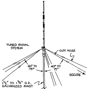
The ATV-3, ATV-4, and ATV-5 may be mounted in any of several configurations. It is important to mount the antennas as "in the clear" as possible, away from any metallic or conducting objects that might interfere with normal operation. The desired mounting configuration will determine which type radial/ground system will be the most efficient and practical.WARNING: THIS ANTENNA IS AN ELECTRICAL CONDUCTOR, CONTACT WITH POWER LINES CAN RESULT IN DEATH, OR SERIOUS INJURY. DO NOT INSTALL THIS ANTENNA WHERE THERE IS ANY POSSIBILITY OF CONTACT WITH OR HIGH VOLTAGE ARC-OVER FROM POWER CABLES OR SERVICE DROPS TO BUILDINGS. THIS ANTENNA, SUPPORTING MAST AND/OR TOWER MUST NOT BE CLOSE TO ANY POWER LINES DURING INSTALLATIONIREMOVAL, OR IN THE EVENT PART OF THE SYSTEM SHOULD ACCIDENTALLY FALL. WHEN THE ANTENNA IS IN USE, CONTACT WITH ANY PORTION OF THE VERTICAL RADIATOR OR GROUND SYSTEM MUST BE AVOIDED BECAUSE OF SHOCK DANGER FROM HIGH RF VOLTAGES. CONSULT THE NATIONAL ELECTRICAL CODE FOR FURTHER DETAILS.
MOUNTING CONFIGURATIONS
- Ground Mounting:
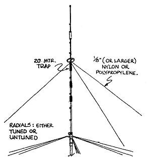
The antenna is mounted just above the ground surface on a short self supporting mast with a maximum outside diameter of 1 3/4 inches. (4.4 cm). There should be no more than 10 inches (25.4 cm) of the support mast exposed above ground before the antenna is installed. Ensure that the mast is driven into the ground enough to prevent any lateral movement afterinstallation ofthe vertical. It is very important that the lower end of the vertical base section is located within 2 inches (5.8 cm) of ground level. Any deviation from this dimension will cause the Nominal Dimensions Chart to be inaccurate. In windy environments the ATV-5 can be given additional strength by attaching polypropylene rope just above the 20 meter trap. (See Figure 4). Do not use any metal wire for the guys. Tuned or untuned radials may be used in this ground mounted configuration. The untuned system provides greater overall efficiency.
- Mast Mounting:
In this arrangement, the antenna is mounted on a well-guyed mast, some distance above the ground (see Figure 5). This method is particularly advantageous for the 10, 15, and 20 meter bands, especially where the antenna is surrounded by trees or other obstacles. In addition, tuned radials should be used, eliminating the requirement for an extensive untuned radial system. Several of the radials can be used as guy wires, providing additional strength for the antenna and mast. The mast can be guyed independently of the antenna; guy wires do not have to be a specific length or broken with insulators as long as they are below the radials.

- Roof Mounting:
This method is very similar to Mast Mounting (see Figure 6). In many cases, mounting the vertical "in the clear" on the roof will provide the most efficient antenna system. As with Mast Mounting, three of the tuned radials can serve as guy wires. (Ensure that the support structure is well grounded through the appropriate ground wires and rods for lightning protection). A special case occurs when the antenna is mounted over a relatively flat, metal roof. ln this configuration, the metal acts as a ground plane, eliminating the need for any radials. The base of the antenna should be mounted as close to the metal roof as possible, with a short electrical connection between the roof and mast mount portion of the antenna.
RADIAL/GROUND SYSTEMS
- CAUTION
- When operating the antenna, ensure that no one can come in contact with the radial system, as a serious shock can result. In addition, make sure that the antenna and radials can not come in contact with electrical conductors, especially power lines, at any time.
- Tuned Radials;
In this system, the radials are used to simulate a conductive ground plane for the vertical radiator. In general, you should use at least three radials per band. The tuned radial system is most effective when used wlth an antenna that is not mounted on the ground, To be effectlve, the radials must be insulated from the ground, except where they are attached to the antenna. For the ATV-4 and ATV-5, it is not absolutely essential to have separate radials for 15 meters since the 40 meter radials will serve as tuned radials for this band. The wires tor the radial system are cut to the correct length, for the desired frequency, by using the Radial Length Chart shown on the following page or by the following formulas:Length = 2970 inches / F MHz -or- 247.5 feet / F MHz -or- 75.44 meters / F MHz
These dimensions do not include any extra length needed for connection to mounting hardware or insulators. The lengths are slightly longer than 1/4 wavelength, to closely match the antenna system to 50 ohm coaxial feedline. ln addition, the angle made by the radials and the vertical radiator will affect the input impedance, and hence the SWR. In general, the closer the radials are to horlzontal, the lower the impedance (often less than 50 ohms), and conversely, the closer to vertical, the higher the input impedance (often greater than 50 ohms). Usually, this is not an extremely crltical consideration, but their position can be used to help adjust the SWR to within tolerable limits.
The radial length should be accurate to within plus or equal to 1-1/2% of the desired length; this ranges from 1-1/2 inches (4 cm) at 10 meters to 12 inches (30 cm) at 80 meters. Satisfactory operation across each band segment will generally result with the radials cut for the center of the desired frequency range, Wire size is not critical, as long as the radials are large enough to prevent breakage, A suggested minimum size is number 22 AWG (0.6 mm).Tuned Radial Lengths
Band
(Meters)Frequency
(MHz)Length
(Inches)Length
(Feet and Inches)Length
(Meters)80 3.500 848 70' 8" 21.55 3.750 792 66' 20.12 4.000 742 61' 10" 18.86 40 7.000 424 35' 4" 10.78 7.150 415 34' 7" 10.55 7.300 407 33' 7" 10.33 20 14.000 212 17' 8" 5.39 14.175 209-1/2 17' 5-1/2" 5.32 14.350 207 17' 3" 5.26 15 21.000 141-1/2 11' 9-1/2" 3.59 21.225 140 11' 8" 3.56 21.450 138-1/2 11' 6-1/2" 3.52 10 28.000 106 8' 10" 2.69 28.500 104-1/4 8' 8-1/4" 2.65 29.000 102-1/2 8' 6-1/2" 2.60
- Untuned Radials:
This system is used in conjunction with a ground mounted vertical, where safe buried or surface radials can be lnstalled. Since the Earth is not a perfect conductor, excessive power is lost in the ground, instead of being radiated by the antenna. By using an extensive untuned radial system, ground losses are reduced, with a subsequent increase in radiated power. The radials are cut to length according to:Length = 2360 inches / F MHz -or- 196.7 feet / F MHz -or- 60 meters / F MHz
Since the exact length is not critical, they may be cut longer or shorter if desired; at least three radials should be long enough for the lowest frequency to be used. Many radials ot shorter length may be used to make the ground resistance as low as possible, particularly in the immediate vicinity of the antenna. Here again, wire size is not critical as long as the radlals are not subjected to undue stress. In a permanent installation, copper, aluminum, or galvanized steel wire is the most suitable for preventing corrosion due to electrolysis.
-
High Conductivity Grounds:
For those fortunate enough to live in an area of excellent ground conductivity, it is possible to operate a vertical antenna without a wire radial system. The antenna should be ground mounted, and electrically connected wlth a short length of heavy wire to a nearby ground rod. As wlth the untuned radials, good conductivity, especially in the immediate vicinity of the antenna, is essential. Ground conductivity is not easily measured. High ground conductivity is most apt to occur in a low, wet environment, i.e. swamps, salt marches, or near large bodies of water. When uncertain of your ground conductivity, it is best to install radials rather than suffer from excessive ground losses.
-
Feedline Considerations:
Use a good quality 50 or 52-ohm cable between the antenna and your radio equipment. An RG-8 type cable is recommended for power levels above 300 watts, or for cable runs longer than about 30 leet (10 meters). You may use the smaller RG-58 type cable at lower power levels and for short feedline runs. In either case, the cable must have a PL-259 for connection to the antenna. After connecting the cable, the connector should be sealed with a silicone sealant and/or electrical tape followed by a coat of clear acrylic spray.The exact length of the feedcable is not critical. In some cases, it may be possible to reduce the SWR at the transmitter by adjusting the length ot the feedline. However, it is best to ensure that the entire antenna system exhibits a 50-ohm base impedance. Since the vertical radiator and center conductor of the coaxial cable are not grounded, the feedline, when not in use, should be disconnected or grounded by a switch for lightning protection. For protection from static buildup, use the Cushcraft "Blltz Bug" Lightning Arrester, Model LAC-l or LAC-2, in the feedline.
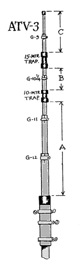
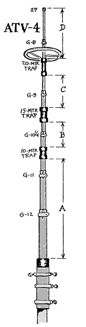
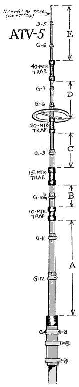
ASSEMBLY lNSTRUCTlONS
 Each Cushcraft vertical has been designed for easy assembly, in addition to efficient operation, each part, and the quantity
necessary, has been described in the preceeding parts list/package. The ATV-3, ATV-4, and ATV-5 are assembled in accordance with
the Nominal Dimensions Chart and diagram on the facing page. Each vertical is constructed of a series of telescoping aluminum
sections starting with 1 1/4" (31.8 mm) tubing for the base selection. The traps and tubing have been integrated, at the factory, into a
single ready-to-use assembly, eliminating any unnecessary mechanical problems.
Each Cushcraft vertical has been designed for easy assembly, in addition to efficient operation, each part, and the quantity
necessary, has been described in the preceeding parts list/package. The ATV-3, ATV-4, and ATV-5 are assembled in accordance with
the Nominal Dimensions Chart and diagram on the facing page. Each vertical is constructed of a series of telescoping aluminum
sections starting with 1 1/4" (31.8 mm) tubing for the base selection. The traps and tubing have been integrated, at the factory, into a
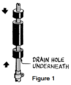
single ready-to-use assembly, eliminating any unnecessary mechanical problems.The various dimensions listed in the Nominal Dimensions Chart will generally permit the antenna to cover a majority, it not all, of the most-used portions of each Amateur band. This will enable you to set the antenna for the designed frequency coverage. Prior to assembly of the tubing, each trap and associated cover is assembied as shown in Figure 1.
Ensure that each trap is positioned so that the drain hole and slots in the tubing are above the actual trap, and the drain hole in the trap cover is below the trap (see Figure 1). Following installation of the trap covers, the telescoping sections are assembled, with the compression clamps used to secure the sections. Referring to the parts list, note that each trap can be identified by the size of the aluminum tubing on which it is installed.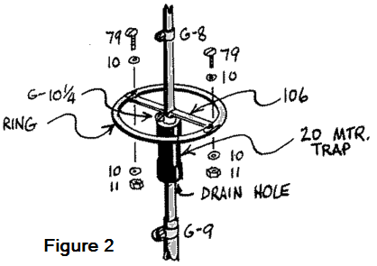 On the ATV-4 and ATV-5, the capacitance ring is assembled as shown in
Figure 2. Placement of the ring is not critical, as long as it is not more than 4 inches (10 cm) above the 20-meter trap. Also, when installing
the ring, ensure that the drain hole in the tubing is not obstructed.
On the ATV-4 and ATV-5, the capacitance ring is assembled as shown in
Figure 2. Placement of the ring is not critical, as long as it is not more than 4 inches (10 cm) above the 20-meter trap. Also, when installing
the ring, ensure that the drain hole in the tubing is not obstructed.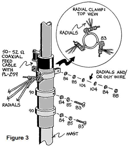 After completion of the vertical radiator, the aluminum mast mount rings and radial/guy wire clamps are assembled onto the base
assembly as shown in Figure 3. Secure the three guy wire/radial wire clamp sections to the base assembly, but for ease of installation,
do not tighten the hardware that holds the radials.
After completion of the vertical radiator, the aluminum mast mount rings and radial/guy wire clamps are assembled onto the base
assembly as shown in Figure 3. Secure the three guy wire/radial wire clamp sections to the base assembly, but for ease of installation,
do not tighten the hardware that holds the radials. As a final step, prior to installation, check all dimensions to ensure that they agree with those from the Nominal Dimensions Chart. If desired, dimensions may be set between chart values, for adjustrnent of the frequency ranges shown by the SWR curves.
NOMINAL DIMENSIONS CHART
- Testing and Adjustment:
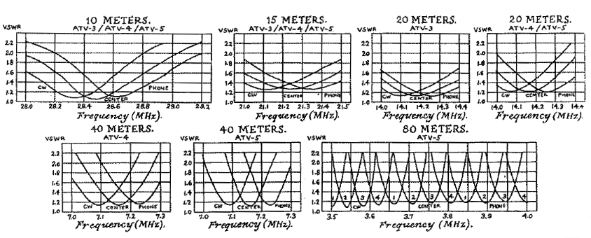
- After assembling and installing your Cushcraft vertical, check the SWR, using low power, to determine if it is tuned to the desired part of the band. There are apt to be slight variations, due to the mounting configuration and radial system, but except for 80 meters, and to a lesser extent 40 meters, these should not be of great consequence. Some variation from the typical SWR graphs should not seriously degrade performance. If the antenna does not exhibit a low SWR at the desired frequency; it can be adjusted by using the Nominal Dimensions Chart and the SWR curves as a guide. For example, adjusting the A dimension will affect 10 meters and, to a lesser extent, all lower frequencies. The B dimension, primarily affecting 15 meters, will not change 10 meters, but does have a small effect on the lower frequency bands.
| SECTION | CW | CENTER | PHONE |
|---|---|---|---|
| A | 101 in (257 cm) | 98-1/4 in (250 cm) | 95-1/2 in (243 cm) |
| B | 17 in (43 cm) | 17 in (43 cm) | 17 in (43 cm) |
| C (ATV-3 only) | 30 in (76 cm) | 30 in (76 cm) | 30 in (76 cm) |
| OVERALL (ATV-3 only) | 14 ft, 1 in (4.28 m) | 13 ft, 10 in (4.21 m) | 13 ft, 7 in (4.14 m) |
| C | 28-1/4 in (72 cm) | 27-1/2 in (70 cm) | 26-3/4 in (68 cm) |
| D (ATV-4 only) | 67-1/2 in (171 cm) | 66 in (168 cm) | 64-1/2 in (164 cm) |
| OVERALL (ATV-4 only) | 20 ft (6.10 m) | 19 ft, 7 in (5.97 m) | 19 ft, 2 in (5.85 m) |
| D | 67 in (170 cm) | 64 in (163 cm) | 61 in (155 cm) |
| E1 (ATV-5 only) | 97 in (246 cm) | 82 in (208 cm) | 67 in (170 cm) |
| E2 (ATV-5 only) | 93 in (236 cm) | 78 in (198 cm) | 63 in (160 cm) |
| E3 (ATV-5 only) | 89 in (226 cm) | 74 in (188 cm) | 59 in (150 cm) |
| E4 (ATV-5 only) | 85 in (216 cm) | 70 in (178 cm) | 55 in (140 cm) |
| OVERALL (ATV-5 only) | 28 ft, 4 in (8.64 m) | 26 ft, 7 in (8.10 m) | 24 ft, 9 in (7.55 m) |