 |
A Homebrew Z-Match Transmatch Craig LaBarge, WB3GCK |
|
A Homebrew Z-Match Transmatch Craig LaBarge, WB3GCK |
|
[Note: The latest version of this article can be found on wb3gck.com.]
Antenna tuners (more accurately referred to as "transmatches") make great homebrew projects; they are reasonably simple to build and, when finished, provide a useful piece of equipment. Every shack should have (at least) one. For this project, I decided to try my hand at building a Z-Match tuner from scratch. This type of tuner has been around for a while. While the Z-match can take on several variations, what distinguishes it from other circuits is that it is a resonant circuit which uses a fixed inductor. Z-Match tuners have become very popular recently with the QRP community, thanks primarily to articles in QRP journals by Charlie Lofgren W6JJZ and the emergence of Z-Match tuners in kit form. Emtech sells their wildly popular ZM-2 kit commercially and the NorCal QRP Club has been selling their BLT tuner kit (a W6JJZ design) like hot cakes. Why the popularity? Here are some advantages that the Z-match design offers:
There is, of course, no free lunch here. Here are some disadvantages of the Z-match design:
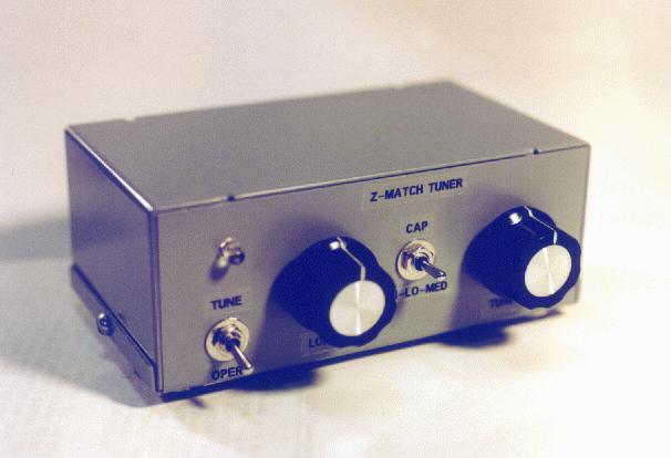
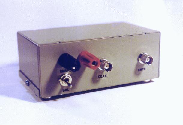
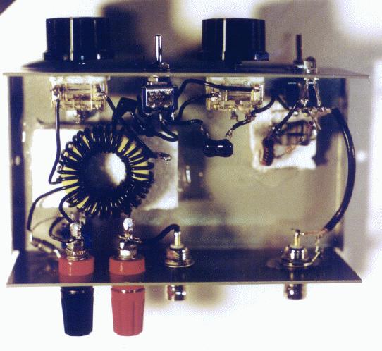
Design and Construction I make no claims of originality for anything in my version of the Z-match. I based it on a classic design which was first appeared in SPRAT #84 (see the G3YCC web site for a schematic of the original design). This design, by the way, is similar to the one used in the Emtech ZM-2. I incorporated a few modifications, however. First, instead of the T-200-2 toroid specified in the SPRAT article, I used a T-200-6 core. W6JJZ recommends the Type-6 core over the Type-2 because it provides a higher Q over most of the HF range. The number of turns have to be adjusted for the Type-6 core, due to differences in permeability. Here again, I went with W6JJZ's suggested turns count. My primary reason, though, for choosing the T-200-6 core was that I happened to have one in my junk box. How convenient! The coil was wound using some #22 solid hookup wire (from Radio Shack) which I had lying around. The secondary winding is wound between the turns of the primary to ensure tight coupling. I added a toggle switch to ground one side of the secondary winding to accomodate single-ended loads, like a random wire. A piece of styrofoam was glued to the bottom of the enclosure to provide some support for the toroid and to keep it away from metal surfaces. Another W6JJZ modification I used was the inclusion of a DPDT (center off) toggle switch to provide some flexibility with the input capacitor. Using this switching arrangement, I can select between one section of the capacitor, both sections in parallel, or both sections in parallel with a fixed 470pF mica capacitor. The extra input capacitance can sometimes be helpful on the lower frequencies. The capacitors are poly film variable capacitors (2 sections @ 365pF each) which were originally purchased from Mouser Electronics. Unfortunately, Mouser no longer carries them and I don't know of another commercial source. I should have purchased a truckload of them when they were available! Similar capacitors with smaller values are still available, if you look around. The SWR bridge I used is a Dan Tayloe LED SWR indicator from a kit which was offered a while back by the Arizona scQRPions. It uses a resistive bridge circuit with a single LED to indicate a null when the bridge is balanced. For the 50-ohm resistors in the bridge, I substituted 2 100-ohm, 1 watt resistors. The bridge will handle a typical 5-watt QRP rig without flinching and could probably handle a bit more than that. The whole thing was packaged in an enclosure which measures 3 x 5 x 2 inches. It certainly could have been built into a smaller package but I had this enclosure on hand and decided to put it to use. On the Air For an initial test, I hooked it up to the famous WB3GCK Downspout Antenna. I normally use an MFJ-941-E ("T" configuration) to load up the downspout. The little Z-match loaded up the downspout on 40 through 10 meters with no problems. On most bands, I could get the LED indicator to go completely out. On one or two bands, I couldn't get it completely extinguished but it did give a definite null. Double-checking with a second SWR bridge indicated that the SWR was 1.5:1 or less in this condition. While tuned up on 40 meters, I had a quick QSO with a station near Chicago from here in southeastern Pennsylvania with 3 watts. Field testing will continue but, so far, it seems to be working fine. |
|