 |
The Pop-Up Vertical Craig LaBarge, WB3GCK |
|
The Pop-Up Vertical Craig LaBarge, WB3GCK |
[Note: After ten successful camping seasons of use, this antenna has been replaced and is no longer in use. For a look at what I am currently using, check out the Pop-Up Vertical 2.0. -- Craig]
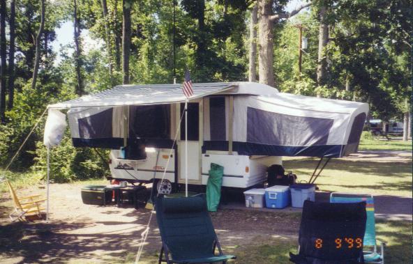
I've always enjoyed combining QRP operation with one of my other favorite pastimes -- camping. After many years of tent camping and stringing antennas through the trees, my family and I have recently stepped up to a pop-up camper. With the new camper, I wanted to try a different approach for a portable antenna to use while camping.
I had a few design goals in mind for this new antenna:
The antenna described here, although still in development, seems to satisfy most of the design goals.
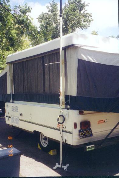
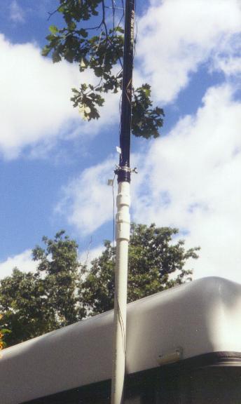
The antenna I wound up with is a base-loaded vertical which uses a 19.5 foot Black Widow fishing rod which supports a thin wire for most of the radiator. The Black Widow rod is supported by an 8 foot mast made of 1-inch PVC pipe. The mast is actually two separate 4 foot sections of PVC pipe which are joined by threaded couplers. In between the two 4 foot sections is a much smaller section which actually supports a loading coil and some capacitors for an impedance matching section. Thus the total length of the vertical radiator from the top of the matching section to the top of the fishing rod is approximately 24 feet. The bottom section of mast threads into a small stand made of PVC pipe which adds a little extra stability while the antenna is being erected. The top of the 8 foot mast reduces down to a length of 3/4-inch PVC pipe which, when wrapped with a layer or two of duct tape, fits snugly up inside the Black Widow rod to support it. The mast section is attached to one of the camper roof supports using nylon cable ties with two wood blocks as spacers between the camper and the mast.
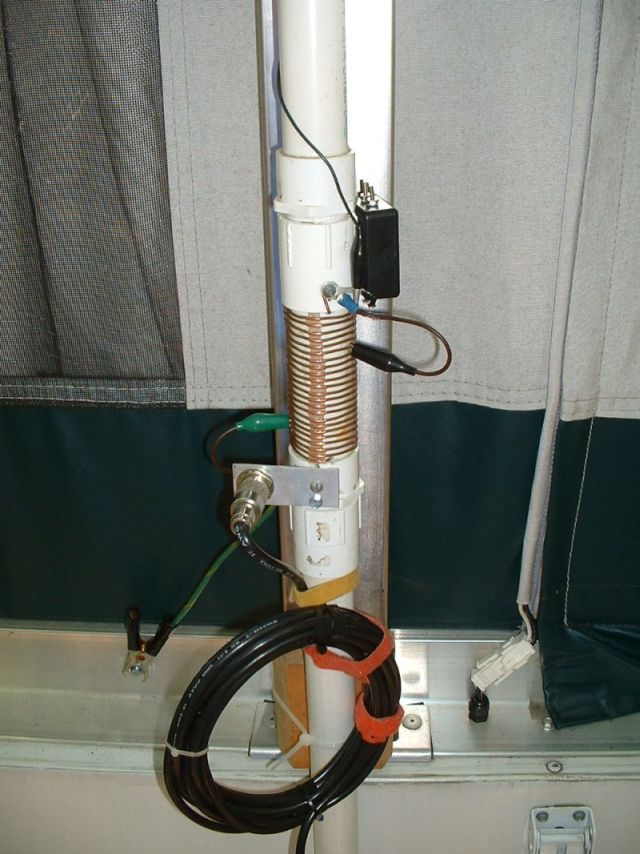
The matching section and its various configurations is shown schematically in Figure 1. The coil is made from 22 turns of #12 copper wire wound over a 3.75-inch section of 1 inch PVC pipe. Inductance and feedpoint adjustments are made by alligator clips. The bottom of the coil is grounded to the camper through a six-inch piece of heavy wire and a large alligator clamp.
To keep things simple and to make band changing faster, fixed
capacitors were used in place of a variable. Tuning is done by varying
the coil taps. The configuration of the matching section varies with
the band being used. Configurations are changed by means of alligator
clips.
40 Meters: On this band, the 24 foot radiator is less than a quarter wavelength and has a capacitive input impedance. Thus, a series inductance is needed to obtain a match.
30 Meters: In this case, the 24 foot radiator is slightly longer than a 1/4 wave and presents a slightly inductive feedpoint impedance. A series capacitor is used to compensate for this.
20 Meters: TBD
17 Meters: TBD
15 Meters: Since the 15 meter band is an odd quarter-wavelength multiple of 40 meters, the matching configuration is similar to that used for 40 meters.
12 Meters: On this band, the matching configuration is similar to the 15 meter case.
10 Meters: On this band, a suitable match was obtained using the series capacitor configuration. It may be possible to get a match with just the coil, however.
Tune-up is pretty straightforward. Once the appropriate
configuration is selected, the two taps on the inductor are varied for
lowest SWR. In my experience, a match of 1.5:1 or better is usually
achievable. Where more than one set of taps produces an acceptable SWR,
I usually go with setting which requires the least amount of
inductance. Table I shows typical settings for the matching circuit.
| Band | Configuration | Coil Tap #1 (# of turns from bottom) |
Coil Tap #2 (# of turns from bottom) |
Capacitance | Typical SWR |
| 40M | A | 20 | 6 | None | 1.4:1 |
| 30M | B | 16 | 7 | 72pF | 1.3:1 |
| 20M | TBD | TBD | TBD | TBD | TBD |
| 17M | TBD | TBD | TBD | TBD | TBD |
| 15M | A | 19 | 6 | None | 1.5:1 |
| 12M | A | 10 | 6 | None | 1.4:1 |
| 10M | B | 8 | 6 | 47pF | 1.4:1 |
The antenna is fed with 50-ohm coax. Near the feedpoint, the coax is wound into a 10-turn coil with a diameter of about 6 inches. This serves to keep RF currents off of the outside of the coax shield.
In practice, I'm able to set up the antenna in less than 10 minutes. Tear down is even faster. The Black Widow rod and the PVC pipe components are stored in a nylon tent bag. On the air performance has been good so far. Signal reports have been very good and European DX has been fairly easy to work on 30 meters running 3 watts. On 40 meters, running 1 watt, the 24-foot antenna has far exceeded my original expectations and doesn't seem to be too bad of a compromise.
So, if you hear WB3GCK/P sometime, give me a call. I'll probably be working you with the Pop-up Vertical.
