 |
Powerpole Polarity Tester Craig LaBarge, WB3GCK |
|
Powerpole Polarity Tester Craig LaBarge, WB3GCK |
|
"The nice thing about standards is that there are so many of them to choose from." - Andrew S. Tanenbaum Anderson Powerpole™ connectors have been widely adopted by Emergency Communications (EmComm) organizations as the standard for 12 volt DC power connections. The consistent use of a standard connector helps to ensure interoperability. If another ham has a power supply fitted with Powerpoles, I should be able to plug my similarly-equipped radio right in and be off in running. No problem. But what happens if the fellow with the power supply didn't correctly follow the standard when he wired up his power supply? Big problem! Here's a super-simple device that will let you check the polarity before you plug in your expensive radio. The key component is a bi-color LED, which changes color depending on the polarity of the supplied voltage. Here are the parts you'll need:
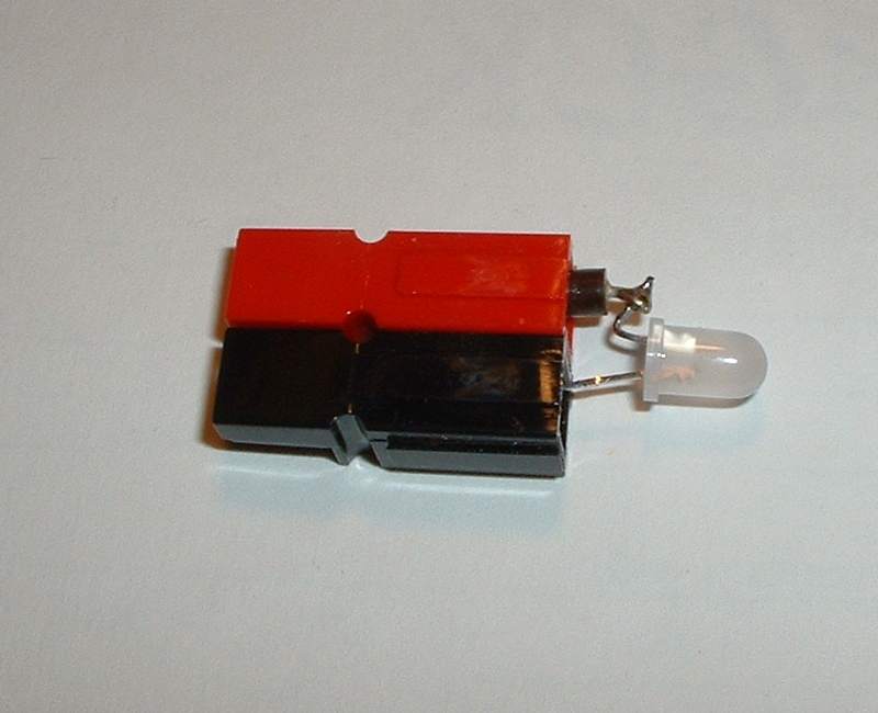
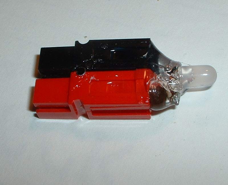
 Assembly is a snap. Just connect up the components as shown in the schematic. The shorter of the two leads on the LED should be connected to the positive side of the Powerpole connector. However, before you crimp or solder the components to the Powerpole connector contacts, check to make sure you have the LED oriented properly. When connected to a 12 volt power source with the proper polarity, the LED light up green. When connected to a source with reversed polarity, the LED should be (yep, you guessed it!) red. When you're sure you have things arranged properly, crimp and/or solder the powerpole contacts and install in the connector body (see Figure 1). Test the completed assembly against with a known, good 12 volt source. I used some Goop sealer/adhesive (see Figure 2) on mine to insulate the bare wires and provide a little extra mechanical stability. For reference, Figure 3 shows the standard Powerpole connector configuration used by ARES and RACES organizations. This whole project took about 10 minutes to build; far less time than it took to write this up. So, for a handful of parts and a few minutes of effort, you can have peace of mind the next time you connect up to an unknown power source. © 2006 Craig A. LaBarge |
Figure 1. Soldered and assembled
Figure 2. Final assembly, sealed with Goop.
Figure 3. Standard configuration for Powerpole™ connectors
|
