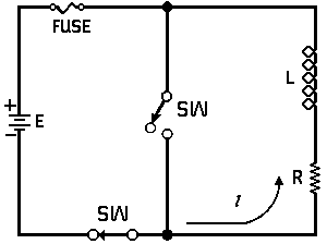
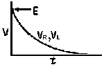
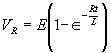
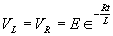
Sw is closed.


|
To Bottom of Page |
Page 19 |
Return to Table of Contents |
HOME |
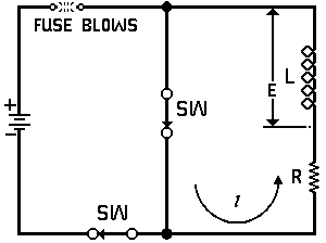
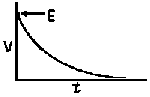
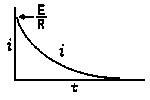
| Voltage is Applied to a De-energized Inductive Circuit | An Energized Inductive Circuit is Short Circuited | |||
|
|
|
|||
| E = applied potential. |
E = counter potential induced in
coil when Sw is closed. |
|||
|
|
|
|||
|
|
|
|
|
|
|
|
|
|
||
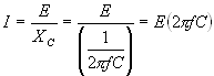
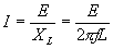
| In a Capacitive Circuit | In an Inductive Circuit | |||||||||
|
In a capacitive circuit, where resistance loss components
may be considered as negligible, the flow of current at a given alternating potential of constant frequency, is expressed by |
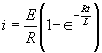
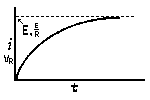
In an Inductive circuit, where inherent resistance and
capacitance components may be so low as to be negligible, the flow of current at a given alternating potential of a constant frequency, is expressed by |
|||||||||
|
|
|||||||||
|
where
|
I
XC E |
=
= = |
current in amperes,
capacitive reactance of the circuit in ohms, applied potential in volts. |
where
|
I
XL E |
=
= = |
current in amperes,
Inductive reactance of the circuit in ohms, applied potential in volts. |
|||
|
Return to top |
PAGE 19 |
Return to Table of Contents |
HOME |