Push Pull Triodes for
Class C
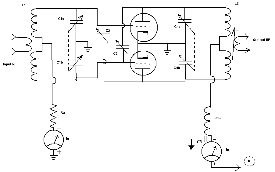
Example Circuit
The purpose of this document is to answer
the question of why things are done in a certain way and why certain components
are used instead of others.
The circuit below is a representation drawing to be used for explanation, but with some refinement could be a working Class C - Transmitter. After the general explanation more drawings will be shown as refinement for a finished product. Please note that the GIF drawings lose some of their detail if shown reduced on screen. You may click on the drawings to show them in a new window and save them for printing.
The GRID TANK:
The link coil of L1 is the input for RF excitation. L1 (known as the grid tank coil) is an air core coil with a center tap on the main coil and a link of a few turns is wound over the top center of the main coil. Because of the tight magnetic coupling to the main grid coil, it is generally not necessary to tune the link separately; however a series or parallel tuning capacitor can be placed on the link if it is desired to produce a specific load resistance to the driving stage that may be more critical of SWR. A small antenna tuner may be used between stages for this purpose. The center tap is not used as an electronic balancing point but instead it is used to provide a grid leak path connection point. At the center of a balanced tank circuit, there is very low RF voltage so it is an ideal point to insert the DC connection of grid leak path.
The balancing of the circuit is accomplished by having equal capacitances from each end of the the main coil to chassis ground. The grid tuning capacitor C1a and C1b provide this balance. It is very important that the "split stator" as it is called, be a balanced capacitor. It must maintain its balance across the tuning range, from minimum to maximum capacitance. The RF voltage that is produced at the ends of the coil must be equal and of opposite phase.
The grid split stator tuning capacitor is generally mounted directly on the chassis providing a connection to ground for the common rotor plates this means that the grid leak DC bias voltage, as well as the RF voltage, will be present on the stator plates with respect to the rotor plates . Care should be taken in choosing a capacitor with the proper spacing from rotor to stator plate in order to handle these voltages without arcing across the gap of the capacitor plates.
The GRID LEAK CIRCUIT:
The exact center of the main grid coil is somewhat difficult to determine and never exact therefore we use a non resonating grid leak resistor (Rg) of composition type, not wire wound (WW), else the inductance of the WW resistor might cause an imbalance of the grid circuit. This also eliminates the possibility of resonating the inductance of a WW resistor with the RF Choke in the plate circuit causing a low frequency parasitic oscillation.
A third advantage to using a composition type resistor is realized when the plate supply voltage is modulated with an audio AC voltage. When the plate voltage varies at an audio rate so does the plate current. This causes a slight rise and fall in the available electrons in the cathode space charge. In turn the grid current will rise and fall as will the grid leak bias. The grid leak bias voltage will follow the modulation voltage in phase at all modulating frequencies. This natural grid modulation is a good thing and helps provide proper modulation. If a WW resistor were to be used it would cause a phase shift of the grid modulation voltage at the higher audio frequencies. This is due to the reactance of the WW resistor's coil. This phase shift is an undesired effect that will make poor modulation at higher audio frequencies.
The Grid leak resistor is determined by the formula Rg = Eg / Ig . Where Rg is the resistors value in Ohms, Eg is the desired grid bias voltage (usually obtained from the tube manuals for the Class C service for the tube that is used), and Ig is the desired grid leak current (usually obtained from the tube manuals, but don't forget to double it for two tubes). The power requirement for Rg is determined by the formula P = Eg * Ig and the resistor should be capable of with standing this for a long period, so I always double the power size of the resistor It is often desirable to use several resistors in some sort of a series / parallel network to provide the power handling capability and desired resistance.
Example:
Desired Bias voltage (Eg) = -200
Desired Grid current (Ig) = 20 ma
200 / .020 = 10K ohms
200 * .020 = 4 Watts
double the power size of the resistor for safety = 8 watt resistor at 10 K ohms
acquire four 2 watt carbon or glass film composition resistors of 10 K ohms each and wire them in a series / parallel network as below
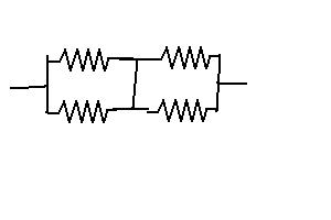
The combined resistance will be 10 K with a power rating of 8 watts but be sure
to leave ample room between them for air flow. This arrangement should
last and give good service as the actual dissipation will be 4 watts of heat and the rating of this
circuit is 8 watts.
Neutralization:
There is a small amount of capacitance between the grid and plate internally in the tubes. These internal capacitances are small - in the range of 1- 15 uuf is typical, but it is enough between grid and plate to cause undesirable oscillations and phase shifts in the the output RF. When the circuit is plate modulated, the phase shifts will move (more or less) as the gain of the tube changes with plate voltage. This will result in phase modulation products on all RF frequencies that come out of the XMTR making the received signal difficult to understand when using product detection and making the signal unnecessarily wide on the dial. Neutralization is the process of canceling out these undesirable effects.
In the circuit at the top of the page, neutralization is accomplished by placing a capacitance - that is equal to the grid to plate internal capacitance of the tube - from the opposite ends of the balanced tank circuits. In this way a RF signal is fed back to the input, but 180 deg out of phase with the previous undesired feedback, therefore canceling it out. This is called cross neutralization.
The procedure for adjusting the neutralization is to first stop all plate current, usually done by disconnecting the plate supply. The plate DC circuit must be open with no path to ground or DC voltage to insure that no RF signal is produced on the plates of the tube that might be due to conduction of plate current. See sub note 2. Then apply the excitation RF to the grid circuit and measure the RF at the output with an oscilloscope or RF voltmeter . The output link should be at its normal coupling and connected to a dummy load else the Q of the tank circuit will be so high as to make the adjustment nearly impossible. Adjust the neutralization capacitors for no output regardless of the plate capacitor tuning. The neutralization capacitors should be equally adjusted so that there capacitances are fairly equal. The best way to do this is to count the turns (See Sub note 5) from their max or min stop positions.
Another procedure that will get you real close to the correct neutralization is to turn the filaments off and disconnect the plate supply. Then attach the antenna that you would use with the transmitter directly to the output link. Then attach the receiver coax directly to the grid input link and tune it to the frequency that the transmitter will be working on. You may want to get a local friend to provide a carrier transmission from his house so you will have something to receive. Now adjust the neutralizing capacitors for little or no signal to the receiver (atmospheric noises will do or a local station transmitting on the desired frequency). This can be done by listing or watching the S-Meter.
When the correct neutralization has been reached and all connections are returned to there normal manner you should be able to apply grid drive excitation to the normal level and grid tuning but when the plate tuning is adjusted across the resonant point with the B+ removed there should be no change in the grid current. Also when the B+ is applied and the loading and plate tuning adjusted there should be a slight increase in grid current as the plate current is dipped with the plate tuning. (See sub note 3) This peak in grid current should occur at the same tuning point as dip in plate current not before or after. If it doesn't then there may be magnetically coupled feedback occurring due to poor physical layout of the tank coils or shielding.
The PLATE TANK:
The plate tank circuit is similar to the grid circuit but with an adjustable link coupling output, used to adjust the loading (See sub note 6), and a RF choke to provide the DC supply voltage path to the plates of the tubes. There is very little RF voltage present at the center tap because of the balance provided by the balanced split stator tuning capacitor whose common connection is chassis ground. Therefore a single RF choke of about 2.5 mh may be used at the center tap of the main plate tank coil. It need not be a low capacitance choke (See sub note 4) but a low capacitance choke does help maintain balance.
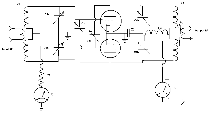
The Plate Tuning Capacitor:
The split stator plate tank capacitor shown in the first schematic above is mounted directly on the chassis and therefore the rotor is grounded. This places the DC + modulation + RF voltage across the capacitor plates making the requirement of plate spacing very large to prevent arcing. A common practice is to mount the frame of the capacitor on insulators and to use an insulated coupling shaft to go out to the adjustment knob. The capacitor frame (rotor connection) must then be connected to the B+ side of the RF choke. This places the same potential of B+ and modulation voltage on both the rotors and the stators of the capacitor so that the only potential difference is the RF voltage. The voltage rating of the capacitor can now be much smaller which makes the physical size of the capacitor smaller. The plate circuit bypass, or decoupling cap as it is sometimes called, (C5 on the schematic) provides the RF path to ground keeping the rotors RF voltage at ground potential thus maintaining the balancing action of the split stator. The revised schematic is shown below.
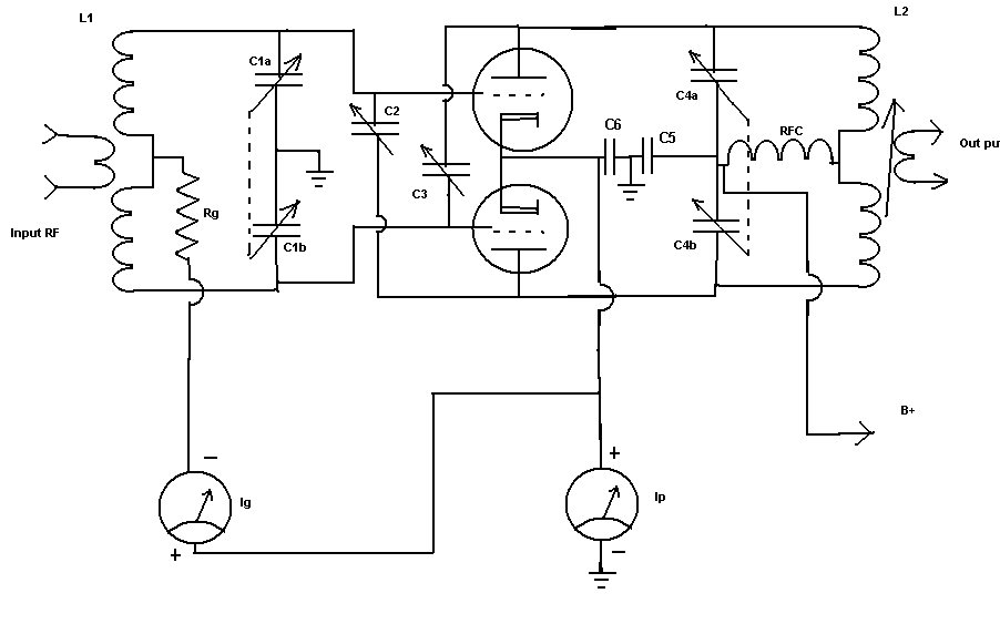
The Metering Circuit:
The next modification will be the metering circuit. You should never put the plate current meter in the HV plate circuit of a transmitter. It is just too dangerous. It should either be in the negative return circuit of the power supply or in the cathode circuit of the transmitter. Placing it in the cathode circuit of the transmitter makes a convenient place to look at it when tuning the plate and load adjustment but it will show the current of the grid and plate added together. You could just mentally subtract the grid current to get the proper reading from the meter or you could return the grid meter to the cathode side of the cathode/plate meter so that it will automatically be subtracted and both the grid meter and the plate meter will have the correct reading. Cathode bypass capacitor C6 will keep the cathodes at RF ground potential. The modified meter circuit is shown below.
Tubes with Directly Heated Cathodes:
Larger transmitting tubes with directly heated cathodes are tubes where the cathode is actually the filaments and there is no separate cathode. When using these tubes each filament connection must be bypassed with a capacitor (C6 and C7 in the schematic below). It is important that the filaments be as close to ground RF ground potential as possible so use multiple bypass capacitor if needed and the filament transformer should be placed as close to the filament connections as is possible. The primary circuit of the filament transformer should have a bifilar wound filter choke with bypass capacitor on both sides (BFL1 in the circuit below). The metering of cathode current in this type of circuit is done on the center tap of the filament transformer. This center tap provides a 60 HZ hum bucked DC path for the cathode circuit. The circuit for directly heated cathode tubes and metering is shown below.

The whole thing:
Shown below is the whole schematic with some other modification. You will notice that there are now parasitic chokes, PS1 and PS2, in the plate leads of each tube these should be of the composition type resistors with about 4-5 turns of wire 1/2 in diameter and 2.5 inches long. These will help in preventing VHF/UHF parasitic oscillations. These parasitic suppressors may not be necessary or they may need to be adjusted in coil size and resistance. The resistors or typically 33 to 100 ohms single or multiple paralleled composition type.
You may also notice there is a capacitor in series with the output link. This used to series resonate the link coil to the operating frequency. If the link coil is resonated then coupling is made easier. If coupling increases then the loading will increase and you will notice that the link will not have to be pushed in as far as before to acquire the same plate current. You will also notice that the plate tuning will not have to be changed to another plate current dip point when the link coupling is adjusted. There is also a RF choke across the output connector to insure a path to ground for any static charge that may build up on the antenna.

All bypass capacitors can be low voltage ceramic except for the bypass capacitors on the primary of the filament transformer (C8 & C9), and the HV bypass capacitor C5. The filament transformer primary bypass capacitors (C8 &C9) will have 110VAC which is a peak voltage of 160V. It is also a good idea to assume there will be a lot of HV spikes on the 110VAC line caused by switching of other transformers and relays in the shack. I would go for a capacitor of 1000 Volt rating for C8 & C9. The plate supply bypass capacitor (C5) should be rated for the DC Voltage Plus the Audio Peak and then some. I like it to be rated at about 3-4 times the DC supply voltage. If plate modulation is to be done don't get the HV bypass too large a value of capacitance as it will cause phase shifts in the audio at higher audio frequencies and high frequency audio will be bypassed as well. Care should be taken in choosing bypass capacitors as there job is to filter or bypass RF. Ceramic capacitor or generally the one of choice and some times multiple smaller values or better than a large single. More is always better on the filaments.
Sub note 2: Due to electron collisions with the plate a small amount of plate current will flow if the plate circuit is connected to the plate supply even if the plate supply is off. This will also happen if the plate supply connection is grounded. This is especially true when RF excitation is present and grid current is showing because the electrons or accelerated towards the plate. The only way to insure that NO plate current will flow is to disconnect the plate supply or B+ connection point leaving the plate circuit completely open. (BACK)
Sub note 3: When tuning the plate tank circuit of the transmitter the plate current will dip when the tank circuit passes through resonance. When out of resonance the plate current will be high and RF output low. The high plate current will be depleting the cathode space charge and causing a reduction in grid current. When the plate tank is resonate and the plated current is low the cathode space charge will be greater and more electrons will be available for grid current flow. Feedback, caused by poor neutralization, will cause the dip in plate current and the rise in grid current to occur at different plate tuning dial points. That is to say that if the grid current should rise as the plate tank is tuned slightly off resonance one way or the other, it would be an indication of poor neutralization or some other RF feedback. (BACK)
Sub note 4: A low capacitance choke is a choke that is wound so that the capacitance between the individual wires, windings, and layers of windings is very small. This type of choke has a higher self resonate frequency than one where care of this nature is not taken. Low capacitance is accomplished by spacing of the windings and breaking up the coils into several smaller coils with spacing for separation. These low capacitance chokes are generally much larger than ones with higher capacitance and the same inductance. (BACK)
Sub note 5: Neutralization capacitors are variable capacitors with small capacitance values. They are insulated above the mounts for both plates and have very fine physical adjustment properties. They are often adjusted by means of a threaded rod with a screw driver slot in one end. Turning the screw will move the plates spacing or change the effective area with a fine precision. (BACK)
Sub note 6: Loading a transmitter is a two step process. First, tuning the plate circuit to resonance (indicted by a very sharp and deep dip in plate current as the plate tuning is adjusted). and second, coupling the RF energy to the antenna or load. Typical if the tank circuit is at resonance but there is no coupling to a load or antenna, the plate current will be very low. As the RF is made to couple to the load, the plate current will not be as low when the tank circuit is at the resonance point. The RF energy that is coupled to the load is taken from the tank circuit and the current in the plate of tubes must increase in order to refresh and maintain that energy. The load coupling adjustment should be made in small steps and after each step plate tank resonance should be checked again for proper dip in current. After the "plate dip" is checked you may increase the loading again. After each step and resonance check you will notice that the current is higher at the "dip". You may continue the process until the desired plate current is reached. The last thing to adjust should be the plate tank tuning for the dip in plate current. If the tank circuit is not resonate the plate efficiency of the transmitter will be poor.
Poor plate efficiency means that the tubes or using more power than is necessary to arrive at the desired RF output level. The plate of a tube will dissipate any input power that is not changed to output and delivered to a load. This dissipation is in the form of heat. Proper tuning and loading will insure this heat dissipation is as low as possible while the desired RF output level is achieved.
Example:
DC plate supply voltage = 1500 volts
DC plate current = 200 ma
.200 X 1500 = 300 Watts input power
Output power = 200 Watts as measured by watt meter on dummy load
(300 Watts input - 200 Watts Output) = 100 Watts
Plate Dissipation = 100 Watts
Plate efficiency = 66 % (200/300)
When using large transmitting tubes a viewing window is often placed in the front of the cabinet to see the color of the plate in the tubes. Some tubes or made to operate at a level where the normal plate heat dissipation causes the plate to show a reddish, to bright orange color. Some tube should show no color. You should be familiar with the tube of choice and make the color check as part of the loading process. (BACK)