a. Turn the equipment ON as
outlined in steps a. and b. paragraph 3.2.3.
b. Tune a communications receiver
to WWV at 10 mc. The BFO in the receiver should be OFF.
c. Rotate the BAND switch to 80 meter band. (lowest scale)
d. Rotate the TUNING dial to 4.0 mc.
e. Rotate the CW-CAL-PH control
to CAL. This turns the VFO, buffer, first and second multiplier stages
ON so that a calibration signal can be heard. Close the telegraph key.
f. Continue to rotate
the TUNING dial about 4.0 mc until the calibration signal is zero beat
with WWV.
g. Turn the FIDUCIAL screw until the hair line is on 4.0 mc.
h. In like manner, the dial can be calibrated on 15,000 kc by setting the communications receiver at WWV on 15 mc and the 32V-3 TUNING dial at 15 mc on the 20M BAND position. See the following table,
| WWV Frequency | Dial Setting | Oscillator Frequency | Oscillator Harmonic |
| 10 mc | 4000 | 2000 | 5th |
| 15 mc | 15,000 | 1,875 | 8th |
| 15 mc | 7,500 | 1,875 | 8th |
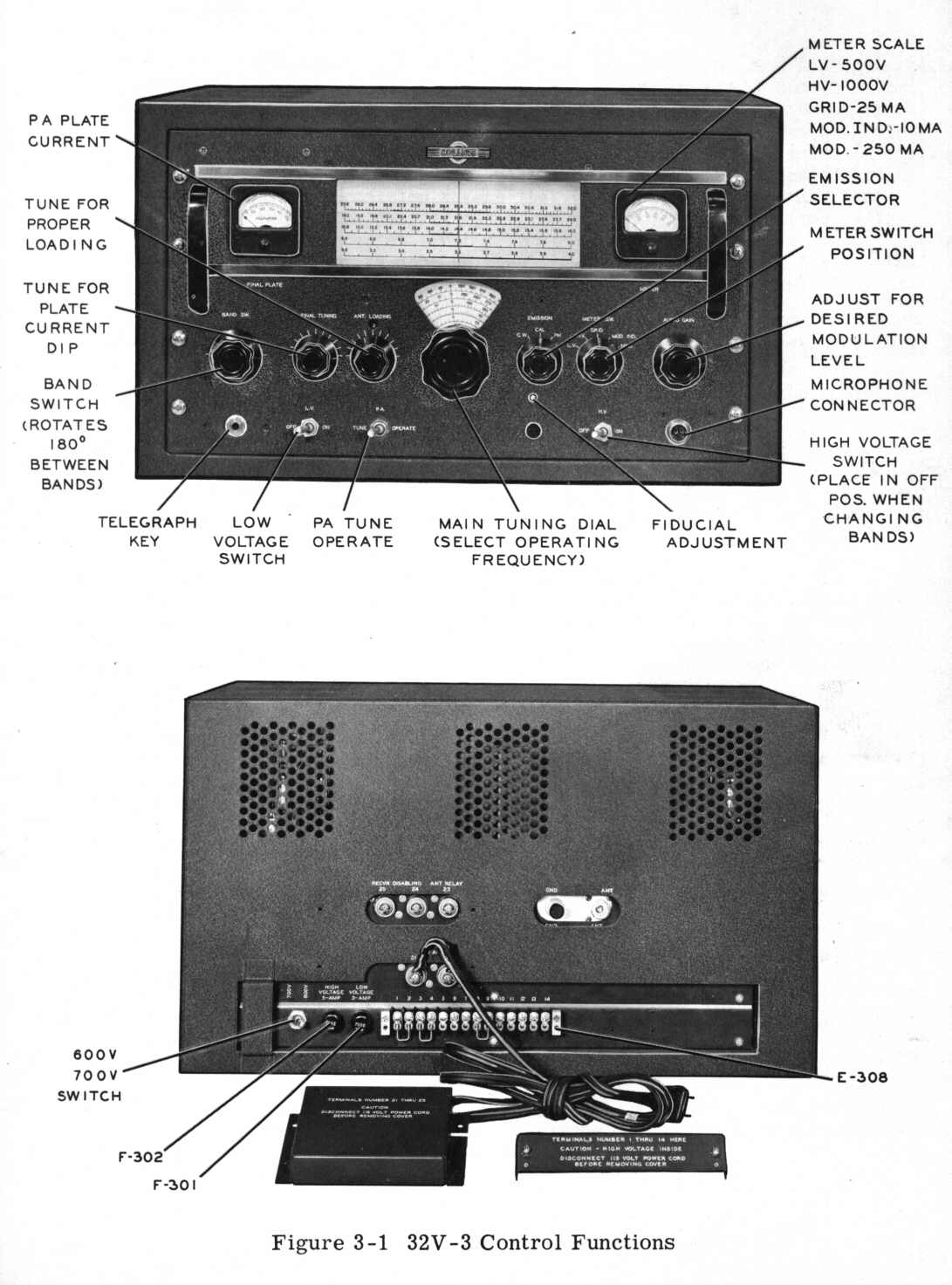
a. BAND SWITCH. - This control selects the proper tuning elements for all stages of the amateur band upon which operation is desired. The knob rotates 180 degrees between adjacent bands. Clockwise rotation selects higher frequency bands. The band selected is indicated by the band lighted slide rule dial.
b. TUNING Control. - This control operates both the slide rule dial and the vernier dial to select the exact frequency upon which operation is desired.
c. CW-CAL-PH Switch. - This three-position switch selects the type of emission required. In the CW position, the secondary of the modulation transformer is short circuited, the screen voltage is removed from the modulator tubes, a bleeder is placed between the PA screen grid to ground and the carrier-control relay is connected so that it can be operated by the HV switch. The transmitter is ready for CW operation when the key is inserted in the KEY jack. In the CAL position, the VFO, buffer, and three multiplier stages are in operation to supply a signal of suiteble strength for zero-beating against received signals without causing interference to other stations. The carrier control relay is disconnected from the HV switch so that the associated receiver and antenna changeover relay will be in the "Receive" condition. In the PH position, the switch opens the short circuit on the secondary of the modulation transformer, closes the keying circuit, applies screen voltage to the modulator tubes and connects the carrier control relay so that it can be operated by the HV switch or a push-to-talk switch on a microphone.
d. METER Switch. - The METER switch selects various circuits to be metered by the meter directly above the switch. This meter has 3 scales: 0-250; 0-500 and 0-1000. The table below indicates how it is used:
| Meter Switch Position | Circuit Metered Reads | Full Scale Deflection |
| LV | Low voltage | 500 volts |
| HV | High voltage | 1000 volts |
| GRID | PA grid current (DC) | 25 ma |
| MOD IND | Mod. grid curent | 10 ma |
| MOD | Mod. plate current | 250 ma |
e. AUDIO CAIN. - This control adjusts the level of modulation in phone operation.
f. LV Switch, - The LV switch turns on the filaments and the low voltage plate and bias supply. (Plate voltage is not applied to the r-f exciter tubes, however, until the HV switch is turned on, except when the CW-CAL-PH switch is on CAL position.)
g. HV Switch. - The HV switch turns on the high voltage supply and connects plate voltage to the r-f exciter tube through operation of carrier control relay K301, The push-to-talk connections are in parallel with this switch.
h. FINAL TUNlNG. - This control is used to obtain resonance of the PA plate circuit. It must be reset after each adjustment of the ANT. LOADLNG controls.
i. ANT. LOADING. - This control is used to obtain correct antenna tuning and loading. Start with this control in position number 1. Usually the 80-meter band will load up on position 1, 2, or 3, the 40-meter band on 4, the 20-meter band on 5, the 15-meter band on 6, and the 10 and 11-meter bands on position 6 of the loading control.
j. TUNE-OPERATE SWITCH. - This switch inserts some resistance in the primary of the power transformer in the TUNE position to reduce plate voltage during the tuning procedure. This switch should always be used to protect the power amplifier tube in off resonance conditions.
k. FIDUCIAL. - This control, a small screwdriver adjustment located directly under the CW-CAL-PH knob, is used to move the vernier dial index during calibration adjustments. Once it has been set, further adjustment will be unnecessary over long periods of time.
1. 600 - 700 v SWITCH. - This switch, located at the rear of the chassis, is used to select either 600 or 700 volts (approx.) for application to the plate.
a. Operate the LV switch to the 0N position. Allow two minutes for the tubes to heat.
b. Turn the AUDIO GAIN to the counterclockwise stop. (off)
c. Turn the ANT. LOADING control to position 1. (minimum loading)
d. Place the CW-CAL-PH control in the position indicating the desired emission.
e. Rotate the BAND switch to
the band containing the desired operation frequency.
f. Rotate the TUNING dial to
the desired frequency.
g. Place the Meter selector
switch in the GRID position and close the telegraph key. (If PH emission
was selected, it will not be necessary to close the key.)
h. Place the TUNE-OPERATE switch in the TUNE position.
i. Observing the FINAL PLATE meter, turn the HV switch ON and quickly turn the FINAL TUNING to resonance, i,e. minimum plate current dip.
j. Observe the GRID current reading on the right hand meter. This should be between 5 and 15 ma.
k. Operate the ANT. LOADING control clockwise until approximately 125 ma loading is obtained while keeping FINAL TUNING at resonance. Repeat this procedure until 125 ma reading is obtained with complete resonance of PA. If it is impossible to load to 125 ma PA plate current, rotate the ANT. LOADING control clockwise until proper loading is btainable.
1. Place the TUNE-OPERATE switch
in the OPERATE position and load the PA to 180 ma with the ANT. LOADING
control maintaining resonance with the FINAL TUNING control.
WARNING
Operation of this equipment involves the use of high voltages which are dangerous to life. Observe all safety regulations. Do not change tubes or make adjustments inside equipment with the high voltage supply ON. Do not depend upon door interlocks for protection but always turn the high voltage supply OFF. SWITCH TO SAFETY.
m. If CW emission is selected, the telegraph key can be opened and the transmitter keyed. If PH (phone) emission is selected, turn the METER switch to MOD. and observe the static (resting) modulator plate current. This should be about 50 ma for the 800 v position of the 600 - 700 v switch at rear (55 ma on the 700 v position). While speaking in normal tones into the microphone, advance the AUDIO GAIN control until the modulator plate current swings to about 100 ma on peaks. This will result in approximately 100% modulation with voice input. If desired, a more exact check of modulation level can be made with an oscilloscope while observing the proper meter swing for the voice of the individual operator.
With sine wave input, the modulator
plate current will read about 200 ma for 100% modulation.
With the METER switch set to MOD.
IND, a slight kick of the needle indicates approximately 100% modulation
on voice peaks. This is useful as an alternate method of indicating modulation
level since no deflection occurs on the meter until the modulation level
reaches approximately 55%. The level at which the meter kicks depends somewhat
upon the loading of the final amplifier and characteristics of the modulator
tubes.
In step g. above, the key plug can be pulled from the key jack since this is a closed circuit type jack.
CAUTION
When changing BANDS, place the HV switch in the OFF position. Also
place the PUSH-TO-TALK switch in the OFF position.
If the 800 - 700 v switch is placed in the 700 v position, the PA
plate current should be 220 ma.
3.2.4. TYPICAL METER READINGS. (PH position withnout modulation.
)
| POSITION OF S305 | LV | HV | GRID | MOD | FINAL PLATE BOTH PHONE & CW |
| 600 v | 240 | 580 | 10 | 50 | 140 |
| 700 v | 240 | 720 | 10 | 55 | 200 |
3.2.5. DIAL CALIBRATION. - when changing BANDS, the proper scale
on the slide rule dial is illuminated automatically as the BAND switch
is rotated. At the same time, the vernier dial fiducial moves up or down
the vernier dial face and stops at the corresponding scale to which the
slide rule dial is positioned.
The dial is read by combining
the vernier dial reading with the slide rule dial reading. The exact method
varies somewhat for the low frequency bands and the high frequency bands
and can best be learned by referring to figure 3-2.
3.2.6. ANTENNA LOADING TABLE. - This table indicates the approximate
position for the antenna loading control when loading into various antenna
impedances on the different bands.
POSITION OF ANT. LOADING CONTROL (for resistive loads)
| FREQ MC | 26 ohm LOAD | 50 ohm LOAD | 100 ohm LOAD | 300 ohm LOAD |
| 3.5 | 2 | 2 | 2 | 2 |
| 4.0 | 3 | 3 | 3 | 4 |
| 7.0 | 4 | 4 | 4 | 4 |
| 7.3 | 4 | 4 | 4 | 4 |
| 14.0 | 5 | 5 | 5 | 5 |
| 14.4 | 5 | 5 | 5 | 5 |
| 21.0 | 6 | 6 | 6 | 6 |
| 21.45 | 6 | 6 | 6 | 6 |
| 27.2 | 6 | 6 | 6 | 6 |
| 28.0 | 6 | 6 | 6 | 6 |
| 29.7 | 6 | 6 | 6 | 6 |