|
|
|
|
|
Columbo and Me |
Door open with |
Internals from back |
|
|
|
|
|
Columbo and Me |
Door open with |
Internals from back |
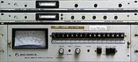 |
(From WERA) From Top to Bottom: Moseley TFL-280 Audio Limiter Moseley TGR-340 Audio Gain Rider Moseley TRC-15 Remote Control System Remote Unit |
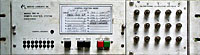 |
(From WERA) Moseley TRC-15 Remote Control System Remote Terminal (transmitter end) |
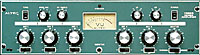 |
(Separate Purchase) Altec 1592B Line Mixer/Amplifier. Has 600 ohm balanced line output. |
REMOTE CONTROL:
The transmitter provides terminals to switch the plate voltage on and off, transmitter on and off, raise and lower
power, and switch crystals. One way to use these terminals would be to run separate wires to the remote control
site, which would be many. The remote control system eliminates this. The receiving unit at the transmitter end
is connected to all necessary control wires for a short distance. The remote control unit is connected to the receiving
end with one coaxial cable. The remote unit sends a "carrier" or signal to the sending unit. The carrier
alone does not perform anything else, but to tell the remote unit that it is present and to light a presence light
on the receiving unit panel. On the remote control unit any of 15 channels may be selected and controlled. Depending
on what operation is performed. When a channel is selected or other function is selected, the carrier signal is
keyed by shifting its frequency. For example, if channel 1 is selected, the carrier is shifted down for one long
period followed by one short period. If channel 15 is selected, one long shift is sent followed by 15 short period
shifts. The receiving unit responds by first resetting, then switching to the appropriate channel.
|
|
|
|
Bottom of transmitter cabinet before cleaning, |
After cleanup using Softscrub cleaner. |
(you have to be old enough to remember that slogan)
|
|
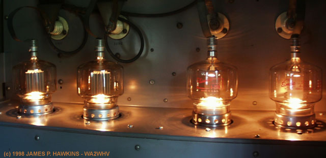
| 220V connected 7/24/1998. Tube lightup test succeeds. |
Initial installation and connection of 220V line completed. The blower, filaments; and associated switches and relays work.
 |
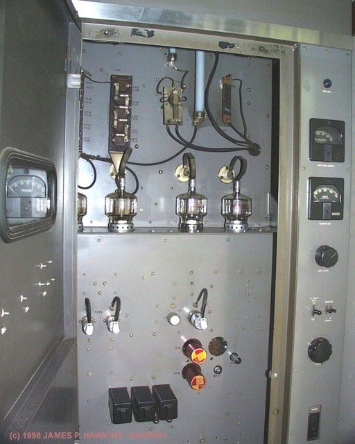
This picture shows that an old standard crystal holder can be plugged into the octal sockets between pins 4 and 6 to replace the oven controlled units. Three crystals can be installed into CR1, CR2 and the Connelrad socket on the right. Front panel and remote control switching is provided for easy QSY, using crystals. In this picture CR1 is 1885 KHZ, CR2 is 1945 KHZ and the Connelrad socket has a 1958 KHZ crystal. The 6AK5 is the crystal oscillator, 5763 is the first amplifier and driver to the 6146 at the top. |
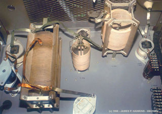 |
Original tuning section configuration. Consists of two PI networks and 2nd harmonic trap. Vertically mounted coil on left is main PI network inductor with tuning slug, adjustable from front panel. Note all capacitors are fixed. |
 |
New tuning section configuration. Second PI network and 2nd harmonic trap coils removed. 100pf tuning cap and dual section 450pf (900pf) loading cap mounted from top grill. Loading cap is shunted with original 1500pf fixed cap and two 100pf resonance caps. The coil is tapped at turn #20. |
OUTPUT RETUNING
I managed to find a 1815 KHZ crystal at a hamfest to replace the broadcast band 1590 KHZ crystal. The output network was modified to use variable caps for easier tuning as shown above. These caps work, but I plan to replace them with larger caps for better tuning range. I picked up the variable caps at a hamfest for $10 each. Threw them in the dishwasher and they came out sparkling clean. (I suggest placing a piece of paper over any labels and taping over them, if you decide to do this. It DOES protect the label on the caps.)
The 6146 buffer output consists of a broadband network with a coil which adjusts by moving a jumper. For 1815, I peaked it on jumper position 7.
 |
Jumper on buffer coil moved to position 7. |
Modulation sounded pretty bad. Above 25-30% it breaks up intermittently and contains a raspy, static-like distortion which got worse with modulation level.
|
|
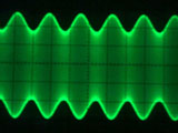
At low a low level of modulation, envelope looks and sounds fine. |
|
|
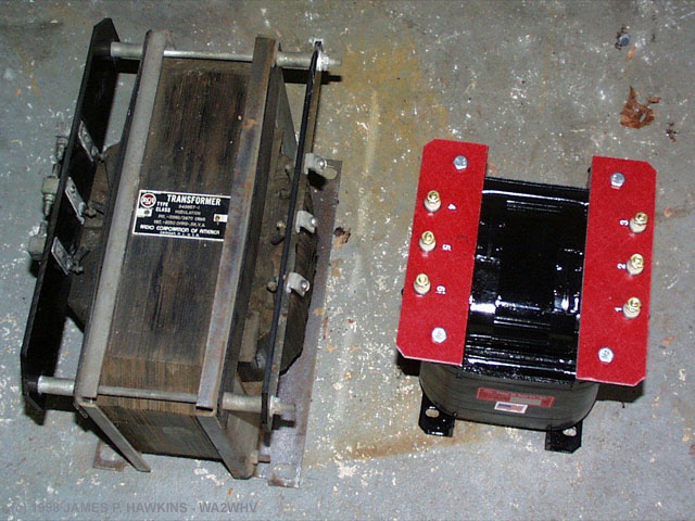
Beyond about 30%, envelope looked like this before transformer replacement. The ragged envelope is the appearance of harmonics due to the fact that the driver stage was pushed to the limit causing clipping (flat tops). The amplification factor of the modulator was severely reduced because of a HV short breakdown in the modulation transformer. This problem was not evident by conventional 110VAC tests on the transformer. |
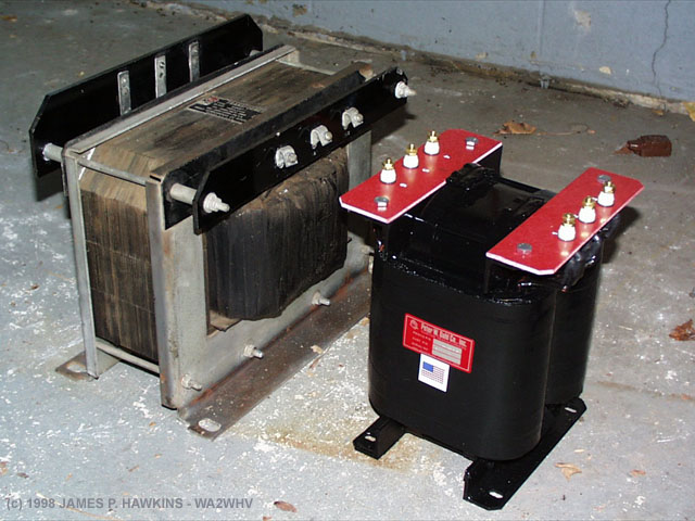
I ultimately borrowed a modulation transformer from Tony Dee's BTA-1R which worked beautifully. I decided to order a Pater Dahl Universal 1KW modulation transformer which was installed on 12/12/1998 and marked the completion of the BTA-500R conversion and repair project. Some friends encouraged me to look for a second hand replacement, but I decided to spend the extra money for a brand new replacement to be assured of longer life and flawless operation.
|
|
|
|
Two views showing original, 110 lb modulation transformer |
|
FIRST CQ
On 11/10/1998 I bought two extension shafts and an 11/16" wood drill bit for my hand drill and managed to drill a hole diagonally through the wall in the corner and through the garage ceiling. I ran a two conductor shielded cable for the audio and a 50' piece of RG-58/U coax for the remote control. After the appropriate amount of messing around I was finally able to turn the transmitter power on and off and key the transmitter from my office. The plate voltage off control in the transmitter did (and still doesn't) work, so I could key it on, but not off. I worked around this by driving an NC relay connected to the remote interlock terminals on the transmitter which results in the same behavior, except that the interlock has to be NC. There was a 30V DC terminal on the back of the control unit which allowed me to drive the relay.
On 11/12 1998 I called CQ for the first time on 1900 KHZ at 1300 UTC. Tha band was not in good condition so I got
no answers. I installed 3, switchable crystals on 1885, 1900 and 1985.
I have the a total of 5 crystals for the following 160 meter frequencies:
All but the 1815 crystals were ordered and custom made by Jan Crystals.
JAN Crystals 800-526-9825: 813-936-2397
P.O. Box 06017: 2341 Crystal Drive: Crystals
Ft. Myers, FL 33906-6017
The oscillator schematic was mailed to Jan for optimal crystal design. The modulation leaves something to be desired.
The modulation transformer is suspect.
First QSO on 1885 KHZ, 11/12/1998 at 00:13 UTC with W3FJJ, Chuck Hanavin, Conowingo,
MD. Signal S9+20.
(This is also my first 160 M QSO ever in my 35 years as a ham.)
12/02/1998 - Tony Dee permitted me to borrow the modulation transformer from his BTA-1R. Upon replacement of the modulation transformer, the transmitter is now fully operational with clean modulation at 100%.
|
|
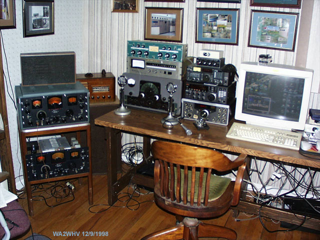
The blue-green Altec Line Mixer and remote control unit on top of the Viking Valiant are my connections to the BTA-500R in the Garage. On the left are 2 SX-28s. The main RX is a JRC NRD-525. Other equipment is an Icom R7000, Ten-Tec Omni-D, MFJ electronic keyer, Dual Pentium 133 and 486/DX-100 computers. |
PRELIMINARIES
SUMMARY OF TRANSMITTER CHANGES