the Salami Merchant - January, 1998
![]()
Next S.A.R.A. Meeting will be held on January 15th at 7:30PM in the basement of the Doylestown Village Hall in Doylestown, Ohio.
Call on 147.390MHz (PL 110.9 Hz) for Directions
![]()
Congratulations
Congratulations to Chuck Dodds, KB8DMT for earning his General Class license. See you on HF Chuck!
![]()
Mars Pathfinder Communications, the Hardware
Continuing in the series about the Mars mission’s communications, this month we will look at the hardware specifics.This information is reprinted with permission from NASA JPL and CalTech.
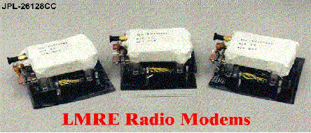
The Radio Modem that is inside the Microrover
Principles of Operation
These radio modems operate, in many ways, just as walkie-talkies do. However, instead of
sending and receiving voice, these radios send and receive data in the form of digital
symbols. The radio modems transmit short bursts of data symbols, termed
"packets", each consisting of 2000 eight-bit bytes. On Mars, the data packets
will transfer rover camera images and engineering telemetry detailing the operational
status of the rover, as well as commands from Earth. Like walkie-talkies, the radio modem
can either talk or listen at any given time, with the direction of the flow of information
between the rover and the lander being controlled by the rover radio modem using a
communication protocol called "half-duplex operation". In other words, the rover
itself starts the telecommunication sessions with the lander, so most of the time the LMRE
radio is in the receive mode.
There are two main parts to these radio modems: the digital portion on one printed wiring board, and the analog portion on a separate circuit board. The digital board acts as an interface between the analog board and the computer inside the Sojourner rover (or the computer inside the Pathfinder lander). This digital board processes the data to be sent and received, and directs the communication protocol, that is, when to talk and when to listen. The analog board, when transmitting data, turns on its 459.7 MHz UHF transmitter and sends out modulated radio waves which correspond to the digital information formatted by the digital board. During receive, the analog board is tuned to radio waves that are the same 459.7 MHz frequency. It amplifies and filters them, and extracts, in a process called demodulation, the digital symbols in such a way that the digital board can input each information bit within a packet as it is received.
The rover radio modem also has a 0.5 W heater attached to its metal frame. This heater is used to raise the rover radio modem's temperature in the early hours of the Martian morning in preparation for the first telecommunication session of the day. This heater was added to the rover radio modem because its crystal oscillator (and that of the LMRE radio modem as well) is not temperature-compensated, allowing the transmit and receive frequency of the radio modem to change with temperature. As the radio modem temperature gets warmer, the transmit and receive frequencies increase; as the temperature gets colder, the frequencies decrease. The maximum permissible frequency shift is on the order of 5 kHz. Testing has shown that when the lander radio runs at about 0�C, the fewest communication transmission errors occur when a temperature difference of 20�C or less is maintained between the rover and lander radio modems. This will be accomplished in part by monitoring the engineering telemetry and issuing commands from Earth to control power to the rover radio modem heater. Typically the lander battery temperature and therefore LMRE modem temperature, will be between 20�C and 30�C for daily operations, so with the rover modem temperature running between 25�C and 40�C we can maintain a temperature difference of less than 20�C. This will be accomplished in part by monitoring the engineering telemetry and issuing commands from Earth to control power to the rover radio modem heater.
Specifications
• Mass: 105.9 grams
• Dimensions: 8.13 cm (3.2") length by 6.35 cm (2.5") width by 2.3 cm
(0.9") height
• RF Connector Type: Coaxial SMA
• DC Connector Type: 9 pin Micro-D (signal and power)
• DC Bus Voltage: +9 Volts, Regulated
• DC Bus Current: 28 mA Standby; 35 mA Receive; 170 mA Transmit
• Operating Voltage: +7.5 Volts
• DC Power: 1.7 W (includes +9V regulator efficiency)
• RF Center Frequency: 459.7 MHz
• RF Channel Bandwidth: 25 KHz
• RF Signal Modulation: DGMSK (Differential Gaussian Minimum Shift Keying), basically
FM modulation
• Handshaking: Half Duplex (Simplex)
• RF Transmit Power: 100 mW
• Computer Interface: RS232 converted to TTL levels
• Maximum Data Rate: 9600 BPS (Bits Per Second) Asynchronous; Effective :2400 BPS
• Temperature Range: -30C to +40C (operational), -55C to +60C (storage)
The LMRE Radio Modem that is inside the Surface Lander
Principle of Operation
The operation of the LMRE (Lander Mounted Rover Equipment) UHF radio in the Surface Lander
is identical to the one in the rover except that it is meant to be powered using a +28
volt source. Therefore it has an extra LMRE electronics board attached to it. Also, the
LMRE radio is attached to the Lander battery case and covered by a silvered thermal
blanket, and does not get that cold at night because internal heaters are used to maintain
the battery temperature. This is an advantage over the rover radio which will need to use
a heater in the early morning hours to raise it to a warmer temperature before we start
communicating. You'll also notice that the LMRE modem has two DC connectors, one is for
power and one is for the signals. In most cases telecommunications and other flight
hardware use separate connectors for power and signals to help reduce the effects of noise
in the signal lines.
 Specifications
• Mass: 265.2 grams
• Dimensions: 10.6 cm (4.2") length by 7.1 mm (2.8") width by 5.3 mm (2.1) height
• RF Connector Type: Coaxial SMA
• DC Connector Types: 9 pin micro-D (signal) 15 pin micro-D (power)
• DC Bus Voltage: +28 Volts, Regulated
• DC Bus Current: 28 mA Standby; 35 mA Receive; 170 mA Transmit
• DC Power: 1.5 Watts (not including +28V DC converter)
• RF Center Frequency: 459.7 MHz
• RF Channel Bandwidth: 25 KHz
• RF Signal Modulation: DGMSK (Differential Gaussian Minimum Shift Keying), basically FM modulation
• Handshaking: Half Duplex (Simplex)
• RF Transmit Power: 100 mW
• Computer Interface: RS232 converted to TTL levels
• Maximum Data Rate: 9600 BPS (Bits Per Second) Asynchronous; Effective :2400 BPS
• Temperature Range: -30C to +40C (operational), -55C to +60C (storage)
The Antenna that is on the Microrover
Principle of operation
The main function of an antenna is to aid in the effective transmission of radio waves
through space. The Microrover's and Lander's UHF antennas work very much like the antennas
on walkie talkies, or on car radios. This type of antenna is referred to as a
"monopole" antenna. There are other type of antennas, for example the round
parabolic dish antennas for satellite cable TV's or the Yagi style TV antennas seen on
many houses. But these antennas are much too bulky for this application. A monopole
antenna has a single (mono) element which is used to transmit the electromagnetic signal.
The radio signal enters the antenna through a coaxial connector located at the bottom,
travels through a short section of balanced coaxial line and is radiated by the monopole.
The coaxial line is balanced by the use of a 1/4 wave choke. The UHF radio signal, like
all transverse electromagnetic radiation, travels at the speed of light (2.997925 x10⁸
meters per second). The rover antenna is on a mast which deploys when the rover stands up
for the first time. Once deployed, it latches into place vertically and remains that way
for the duration of the mission. The height of the rover antenna when it is deployed is
about 83 cm.
Rover Antenna Specifications
• Overall Length: 45.0 cm (includes support tube)
• Materials: Fiberglass tube, Aluminum Tube, Teflon supports, coaxial cable
• RF Connector Type: Coaxial SMA
• RF Center Frequency: 459.7 MHz
• RF Bandwidth: 700 KHz for < 2:1 VSWR
• RF Gain: 1.4 dBiv
• Free Space Match: 1.09:1 VSWR at center frequency
The Antenna that is on the Surface Lander
Principle of Operation
The LMRE antenna works very similar to that of the rover antenna. The one exception is
that it is not a deployable antenna. Its position is fixed on the support structure next
to the LGA antenna.
LMRE Antenna Specifications
• Overall Length: 33.6 cm
• Materials: Fiberglass tube, Aluminum Tube, Teflon supports
• RF Connector Type: Coaxial SMA
• RF Center Frequency: 459.7 MHz
• RF Bandwidth: 16 MHz for < 2:1 VSWR
• RF Gain: 1.4 dBiv
• Free Space Match: 1.25:1 VSWR at center frequency
As space and time allow, the Salami Merchant will carry more details about the Mars mission communications systems.
![]()
Bob Bohn is in Volunteer Spotlight
This article is a reprint from the Medina County Gazette, 12/23/97by Cheryl Rocco, Services Director
Bob Bohn has been active in our disaster services program of the American Red Cross of Medina County for the last four years. He is presently disaster communications chairman and a member of the disaster action team.
When not actively volunteering for the Red Cross, Bohn is employed at MATS Imaging Technologies as a senior service engineer, specializing in the installation, repair and maintenance of nuclear gamma cameras and video image processor computer systems.
He attended the University of Akron, earning an associate degree in electronics technology and presently holds an FCC technician class license for amateur radio. He is a member of the American Radio Relay League and in May, he received the Exceptional Volunteer of the Year Award in disaster services.
Bohn's interest in becoming a Red Cross volunteer began approximately four years ago when he approached our former director. During the interview, she learned he was a member of the Silvercreek Amateur Radio Association and asked if the group would like to provide communications for a mock disaster operation scheduled in March 1995. He informed Silvercreek of this opportunity and they participated in this mock disaster.
From that point, Bohn began to take Red Cross training and eventually accepted the communications chair two years ago.
Bohn also had a dream. The dream was to apply to the FCC for a radio license for the chapter. Stuart Root, a board member, had been instrumental in securing a communications pole for the chapter, but we needed the license and the equipment to make this dream come true. Bohn completed the paperwork the FCC requires and we waited for approval. Meanwhile, he began to buy and repair used equipment as soon as funds were available.
Soon his dream started to become more of a reality.
Finally, our FCC license was received. We were able to mount needed antennas on the communications pole and were in business.
During our tri-county mock disaster exercise this past spring, we were able to test our communications equipment and passed with flying colors.
We are still in need of equipment. If you arc interested in donating, contact Bohn at the American Red Cross of Medina County at 225-4300 or 723-4565.