CABLES/CONNECTORS
The Heathkit manuals are of course excellent and should be referred to both for wiring instructions and detailed explanations of how the circuits work.
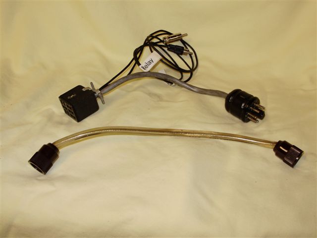
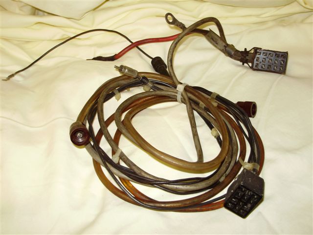
This is an ultra-short cable set for the HP-24 A.C. Power Supply. The main cable between the power supply and the amplifier shows both the relay and ALC phono connectors.
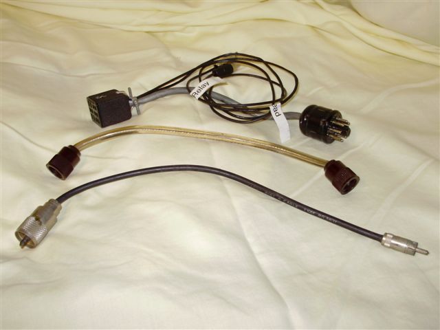
Cable Set for the HP-14 D.C Power Supply
1) The coaxial antenna cable: Little needs said about the antenna cable except to remember the HA-14 does not have a Loading control; only a Tuning control. The loading is fixed at 50 ohms. This does not usually cause a problem as long as the antenna is properly tuned and shows a low SWR to the amplifier.
SWR is turn is not usually a problem with an ordinary dipole fed by matching ~72 ohm coax, or a beam or vertical or other antenna matched to a ~50 ohm cable. The problem may arise using a mobile antenna which can exhibit a wildly varying SWR depending on care in tuning, by movement in the wind, or tuning the transmitter to a frequency outside its narrow bandwidth.
While RG-8 or RG-9 coax would be preferred, I have experienced no problems running full SSB power to either the smaller RG-58 or RG-59.
2) The Low Voltage and Control cables: These cables carry the ON/OFF switch control, 12 volt filament power for the 572B's, a line that controls the antenna relay, and another for the ALC circuit.
The connectors on the supply end of these 8 conductor cables (Belden 8448 ???) are different for the AC and DC power supplies:
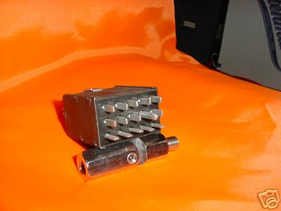
A 12 pin chassis mounted Jones plug is used on HA-14 to receive power from either supply.
A 15 pin chassis mounted Jones plug is used on the HP-14 DC power supply to furnish the lower voltages and for control circuits.
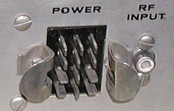
A chassis mounted Octal Socket on the HP-24 AC supply delivers the low voltage power and control.

None of these cables or connectors require special attention here.
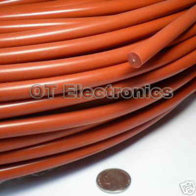
3) The High Voltage Cable & Connectors: A separate cable made of Belden 7766 high voltage wire or similar is used to connect the +2,300 Volts from either power supply to the amplifier.
Since cables deteriorate with age, they and the HV connectors on both the cable and power supplies should be carefully inspected before use. Cracked or damaged HV components should be replaced.
The HV chassis and cable connectors are Millen 37001 C and D in the red matching pair:
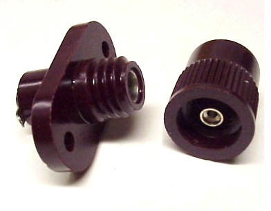
Belden 7766 cable seems to be no longer available but other 7 mm diameter HV cable can be found on eBay and elsewhere. Some users report using ordinary spark plug wire, but caution is urged in any case. The Millen connectors are available.
Auto parts houses no longer sell spark plug wire by the foot, stocking it instead as part of complete wire sets packaged for specific vehicles. But private garages, and motorcycle, golf cart, snowmobile, tractor and lawnmower repair shops may keep a spool. eBay often shows inexpensive new plug wire sets.
When buying any HV wire for the HA-14 it's important to check the wire dimensions for a good fit to the high voltage connectors. Also, be sure the 'wire' is real copper wire, not nichrome resistance wire, nor a carbon trace used for spark plug RF noise suppression.
4) Transmitter-Amplifier Cable: Hooking most tube type Heathkit Transmitters/Transceivers of that era to the HA-14 Amplifier is a piece of cake. They are designed to work with each other. Just follow the cable wiring instructions in the manuals.
But hooking any modern solid state transceiver to any sparky old high voltage tube type amplifier should cause a moment of pause. There are more than a few reports of blown transistors when such a connection is attempted.
There are several solutions to this potential problem. They involve isolating the two electrical systems, usually by a relay of some sort.
1) One solution is to use an "Amplifier Interface" of the sort made by Ameritron. This involves a separate isolation box which goes between the units. Download their users manual for useful information on interfacing.
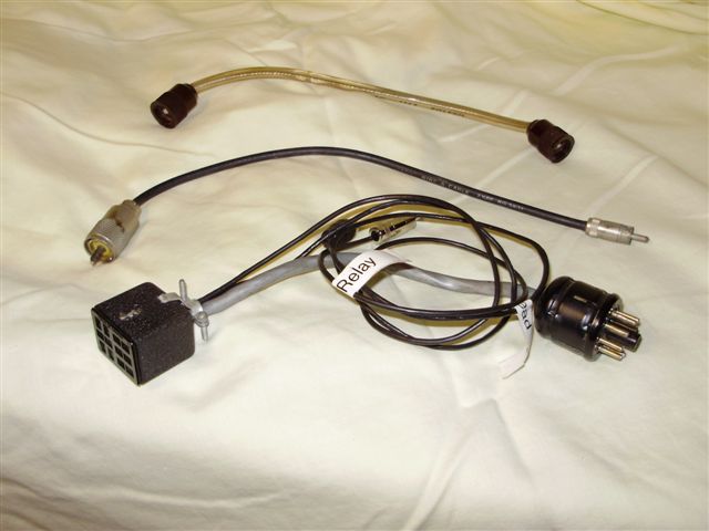
2) Another solution is to use a custom cable which includes a relay built into one of the connectors. K8TJ builds and sells such "amplifier relay cables". He sent along some interesting comments and opinions on this subject which you can read here.