|
|
||
01/02/07 |
 
|
"W4XE Repeater Tech page ©"
UNIDEN ARU251KT
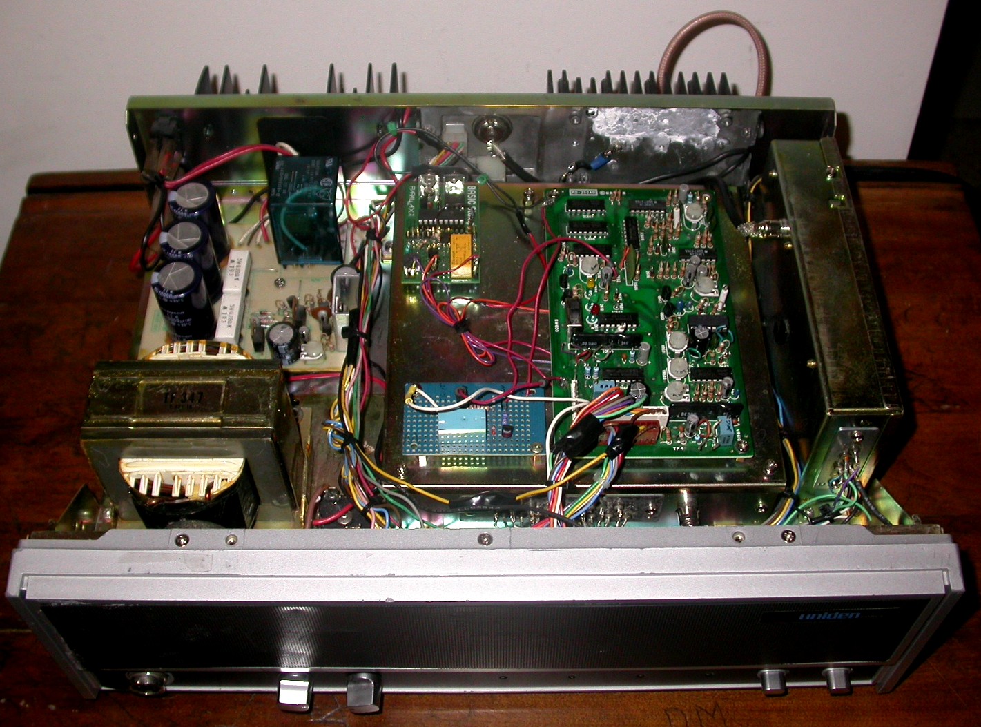
Information about the UNIDEN series of commerical radios for ham radio use is about non-existent on the web. So I thought I'd include some information about them on my website. The ARU251KT is a crystal controlled desktop UHF 25 watt repeater complete with AC/DC power supply, controller and small duplexer. An optional auto-patch controller was installed in the bottom of the unit. It comes equipped for emergency battery backup power from an external battery source. It has PL encode and decode capability (tunable pots). A community multiple PL option card was available as well. Portions of the UHF repeater manual are available in PDF format. There is a VHF version called the ARH-351. Typically a 5 MHz split using a mobile duplexer is used. Another is the ARX-700A looks similar as well. Specs TBD. Also there is the newer Uniden MRS 804 A/S/T 800 MHz LTR desktop Repeater The repeater is intended for light 20% intermittent duty usage. A lot of people try to press these into continuous duty cycle applications and burn up the RF PA or AC power supply. This is why you'll find a lot of these on the used market with a blown PA (beware!). The good news is that the PA sub-assembly can be found in the FMU-250K UHF mobile shown below. However, the mobile does not share RX and TX modules with the repeater as the mobile is synthesized. Below is the pin out of the rear panel accessory connector:
This should be sufficient to attach an external controller. Here are some links to another website on interfacing the uniden repeater:
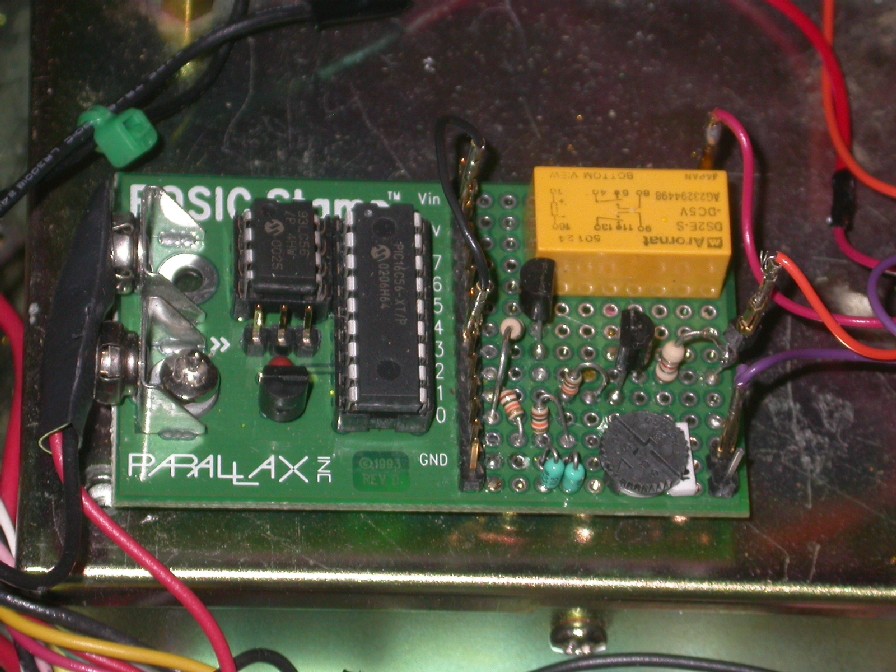
Uniden ARU 251 Repeater to External Control Mod pkg. Uniden ARU 251 Modification, text only. The controller in the ARU251 repeater is a bare bones unit with TAIL and TOT. No CWID is provided in the stock repeater. I added a small Parallax Basic Stamp to provide CWID and courtesy tone. Parallax and Digikey sells these handy little Basic stamps. These microprocessors are serially programmed from your computer. The 'Basic' language software contains the hard coded call sign. The call sign can be easily changed in software in a few minutes. The proto area on the stamp was used to provide space for the transistor buffers, relay and filtering the CW audio output. Below is a schematic showing this circuitry. The Stamp was mounted on top of the lid of the receiver next to the control board. If you look closely, you'll notice the RF PA is missing on this particular ARU251 rear deck. Unfortunately, before I got a hold of the repeater, someone had already blown the PA. I removed the PA and directly wired the 250 mW exciter to the RF output connector on the back of the repeater. I used a previous project's AMP when I had built up an external amplifier using one of the MHW type 250 mw to 20 W brick modules. See www.rfparts.com for some suitable modules.
Closing comments: As I noted above, one of the weak points of the repeater are the RF PA's. Uniden used the rear module assembly and heat sink directly off a mobile radio. This is probably sufficient for the 20% duty cycle use, but people press them into a higher duty cycle application and fry the PA. Ditto for the internal AC power supply. I've seen a number of these repeaters with dead AC supplies. Fortunately the repeater is already setup to provide an external 12 VDC for emergency power. I would definitely consider adding some external fan cooling on both the RF PA and Power supply heat sinks on the rear of the repeater. About half of the repeaters I've seen for sale are missing the small internal duplexer. The radio may have been sold as a base station instead of a repeater. If you are considering purchasing one, check all of these things out when considering how much the unit is worth.
UNIDEN FMU250K
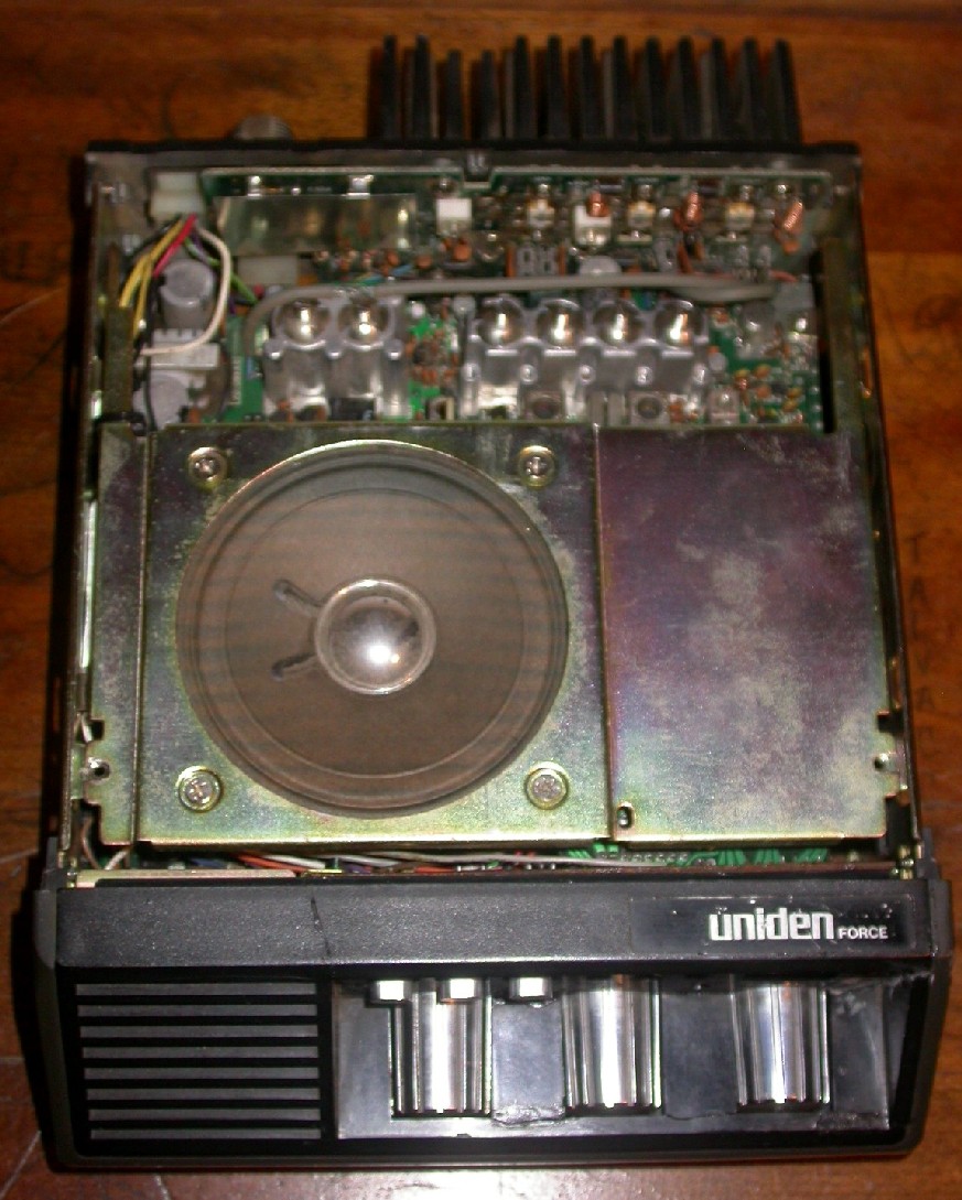
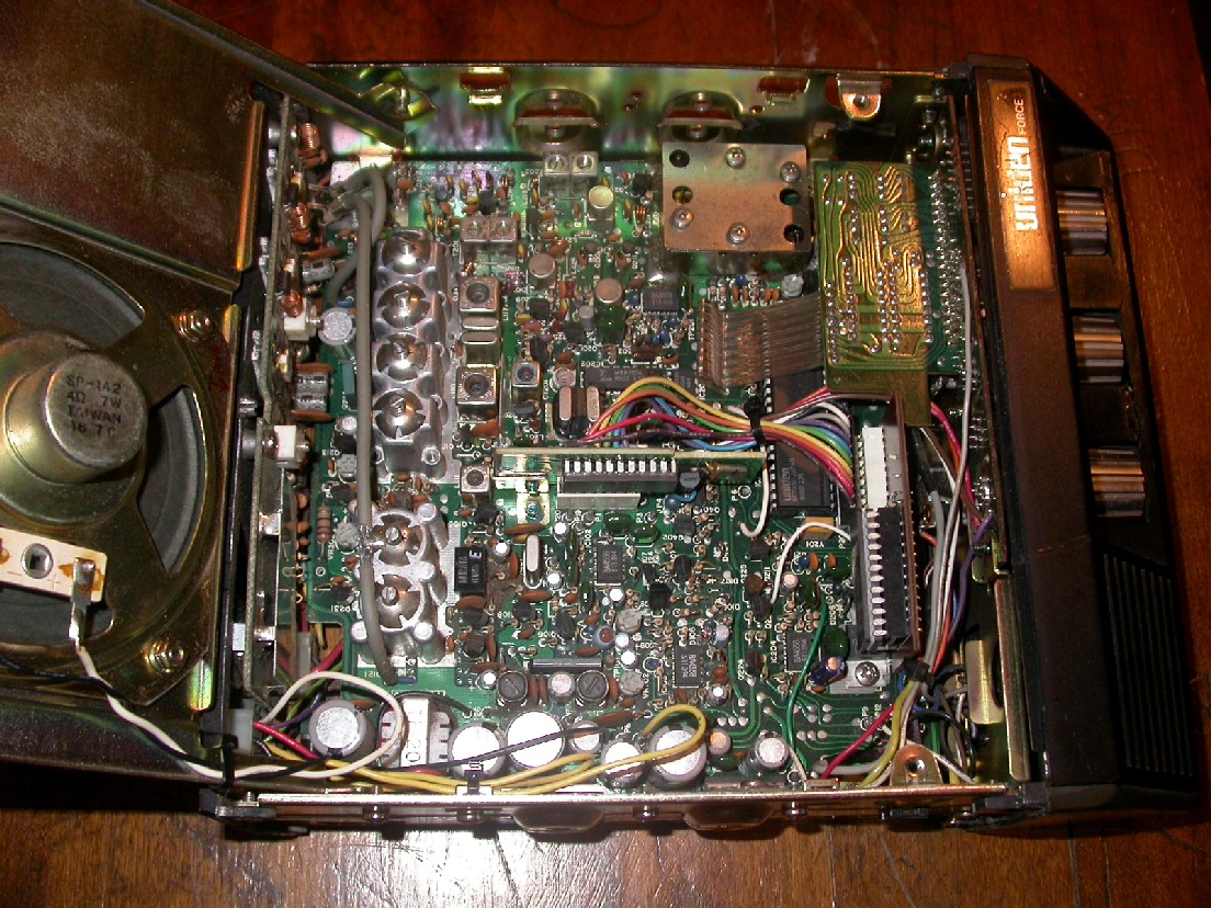
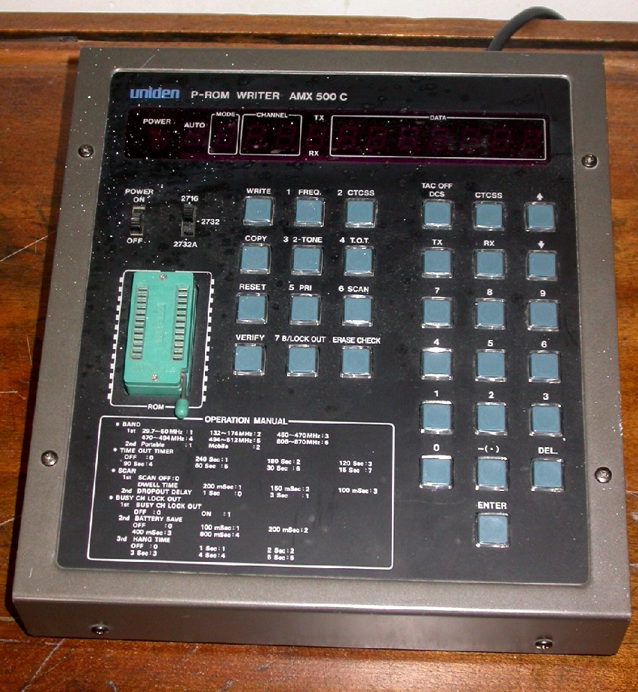
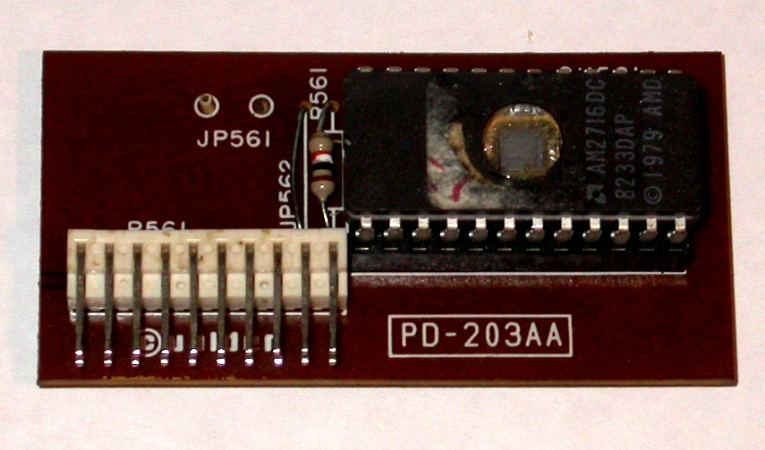
The FMU250K UHF 450-470 25W is an 8-32 channel synthesized FM Mobile Radio. It can only be reprogrammed using an EPROM Eraser and a UNIDEN AMX-500C programmer. I don't currently know of anyone who's decoded the hex file yet for a PC software approach with a generic EPROM programmer solution. That would definitely increase it's aftermarket value and popularity. Be advised that there are several models of this radio that all 'look' identical from a first glance. The Model number is stamped on the rear heat sink of the radio. There is the AMU and FMU series of UHF radios. The FMH is the VHF version of the FMU. There are crystal only versions of the mobile (AMU). There are low and high power versions. There are diode programmed matrix radios that are synthesized. Then there are the ones shown above that are EPROM reprogrammable. The newer series of UNIDEN's were fully software programmable using adapter cables off the AMX-500C programmer shown above. There are low band, VHF and UHF versions of radios. Also there are 800 MHz versions (FMU250KT is an 800 MHz version not to be confused with a UHF FMU250K!). Reprogramming the radio: The FMU250K uses an inexpensive 2716 or 2732 type EPROM depending on number of channels utilized. 1. Carefully remove the EPROM plug in board from the radio. Use a small screwdriver to remote the EPROM from the plug in board. It can be used to pry it up at each end a little at a time. Don't bend the pins!
2. Remove the window sticker on the EPROM if it is covered. Use a UV eraser to erase the EPROM. Typically it takes 15-30 minutes depending on your model of eraser. I use a Spectroline PE-14. 3. Enter the desired frequencies and PL encode/decode tones into the AMX500C programmer shown below. 4. Insert the EPROM into the AMX500C programmer and reprogram the EPROM.
The AMX500C will only program F series portables and mobiles and the SMU300K, SMH400D 5. Replace the EPROM onto the plug in board. Reinsert the memory chip board into socket on the radio.
6. You'll have to retune the front end of the receiver for maximum sensitivity and perhaps touch up the VCO as well.
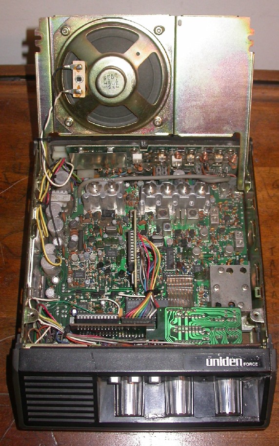
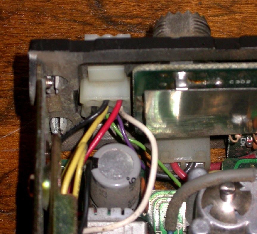
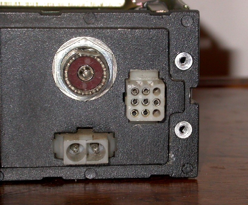
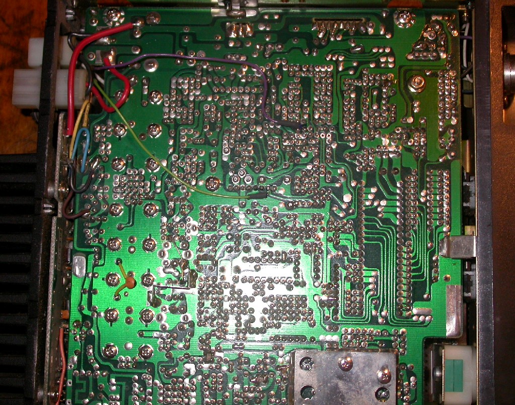
Uniden FMU250K Ralph Hogan W4XERemote Base ModificationsI am currently planning to utilize some of these FMU250K radios as link radios. They easily retune to the 440 MHz Ham band. The price is right, you can usually find the mobiles for $10-$20 and I already have the AMX500C programmer. Unlike the GE Phoenix SX, all of the connections you will need for remote base use are not brought out to a connector. You will have to tap into the radio for access to RX audio, COS and PL detection signals. There are several options listed below. Fortunately the rear panel Molex connector J504 has several unused connector pin positions. Slide in some extra 0.062" Molex female pins (Radio-Shack or Digi-key) and you are in business. You must be careful to not load these signals with your external repeater controller circuitry. I inserted a series 10K ohm resistor in the COS and PL lines inside the radio. A simple 2N3904 buffer/inverter circuit will also work nicely with the COS and PL signals. TX Audio & PTT: For TX audio and PTT, you can use the front microphone connector. It's a standard round 5 pin microphone style connector. I scrounged a cable from an old microphone.
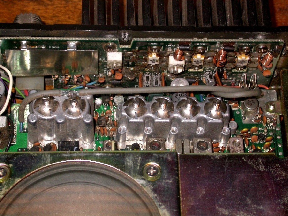
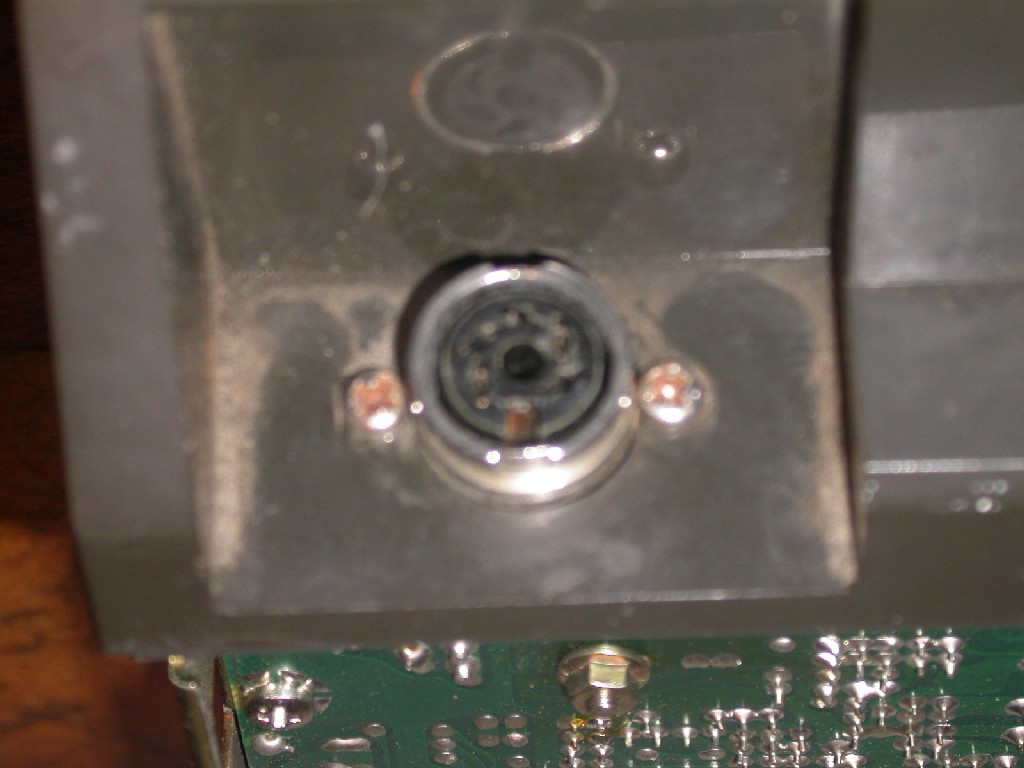
RX Audio: Test Point P16 is muted audio. Varies with the Volume pot. You can disable the local speaker by cutting the loop wire on the outside molex J505 pins 4&5. I installed a switch there to re-enable the local spkr audio for test purposes. The signal varies from 100 mVp-p to 1-2 Vp-p with volume control action. Due to the audio circuit design topology, unfortunately you will have to preset the volume pot and leave it alone during remote base use. P5 & P8 are audio output to speaker. Yellow wire connects to J505-5. 100 mVPP to 2 VPP with volume control action. RX PL Detect: Pin 7 on J401. 0 VDC no pl, 5 VDC active high PL tone detected. J401 is the connector the PL board plugs into. The plug in PL deck is in the very center of the photo below.
RX COS: There are a few tap points to consider: PIN 1 on IC103 No sig 1.3V, Signal active high 6.9V. Microprocessor Pin 28 no sig 0.9V, Signal 4.6V ACTIVE HIGH These two access points (IC103/uP) are too high a DC value in the inactive state to drive a buffer transistor without an additional voltage divider. Q109 is the squelch switch. Collector=0V sig, 5.5 No sig ACTIVE LOW This is the best point for driving a transistor input buffer stage as the signal detect is near zero VDC. Q109 center pin is the collector. Two resistor R168 / R167 are in front of the Q109 (towards radio front) they are both 10K. Scrape off the top coating of R168 and use that as the test point to find COS. I then located this point on the bottom side of the pcb.
Note: PIN 5 Channel Guard Disable (Remove ground from hand mike hang up button) The 5 pin din connector shield is ground as well. COS & PL Wiring notes: To gain easier access to the J504 for inserting new pins, you can remove the Molex connector from the back panel. Push in on the plastic wing tabs and the connector will slide back into the radi. Below shows J504 and the new pins that were added.
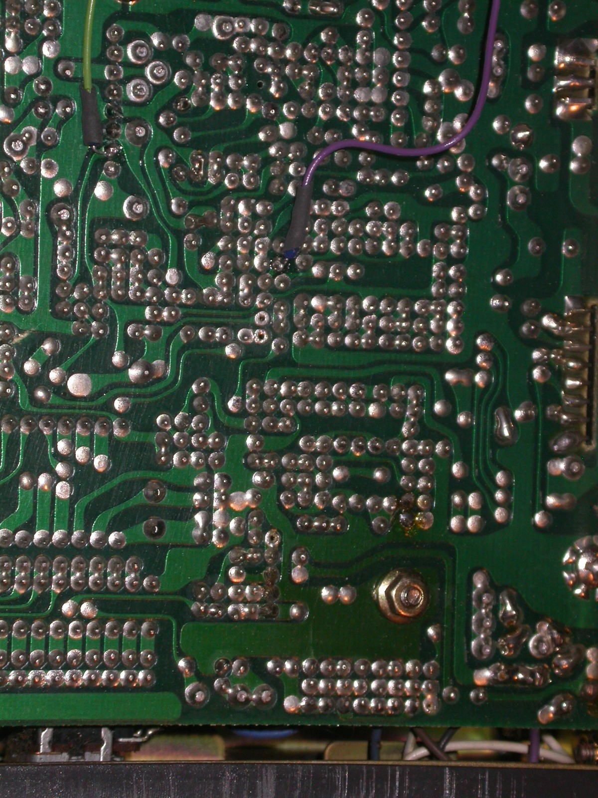
I routed two wires for COS and PL from J504 onto the underside of the PCB. I highly recommend having the appropriate service manual available! The purple wire is for COS collector (center pin) of Q109. It will provide 0 VDC active signal detect and 5.5 VDC no signal detected. The green wire is the PL detect Pin 7 on J401. It will provide PL detect active high 5.0 VDC when a proper PL tone signal is received. Below are several views. Note the series 10K ohm resistors just to make certain we don't load the signals down.
When completed you are ready to hook up to your favorite repeater controller.
73's Ralph W4XE 01/02/2007
|
|||||||||||||||||||||||||||||||||||||||||||||||||||||||||||||||||||||||||||||||||||||||||||||||||||||||||||||||||||||||||||||||||||||||||||||||||||||||||||||||||||||||||||||||||||||||||||||||||||||||||
This site was last updated 01/02/07