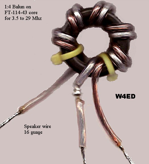
Made from Amidon FT-114-43 core, 16 gauge speaker wire, and tie wraps,
this balun is less than 1 1/2" in diameter and quick to fabricate.
Two were made for purpose of loss measurements. The loss was measured
via the two balun back-to-back ( 50 ohms in & out) method. Loss
was less
than 1.5 dB each, across 80m to 10m. Continuos 50 watt
RF power was applied
to the back-to-back test configuration for several minutes with
no
heating or arcing.
SWR was measured with Autek RF-1 by driving a balun on one side and
placing a 220 ohm carbon resistor on the other. SWR
was less than 1.2 : 1
across same range, and could have been even better, because the
resistor
value was not ideal.
The balun is currently in use at the feed point of a 40 m Off Center
Fed Dipole.
That dipole is doing well for K4SID, its up ~ 35 feet,
has 27'2" and 37' legs,
is fed by RG-8X and an antenna tuner. He made a weather
proof housing
from readily available PVC plumbing materials.
The core was purchased from Tech America # 900-700, Amidon
FT-114-43.
Speaker wire (zip cord) was from Best Buy, 16 gauge, with thick
insulation
compared to other 16 gauge speaker wire samples.
Following graph show simulated radiation pattern for
the OCF dipole on
four bands. The simulation included a nominal urban
soil for ground.
How about a small loop hung on a fish'n pole ??
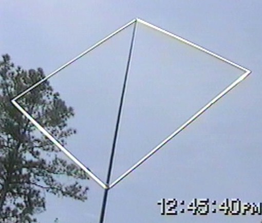
Small Loop for 14 - 28 Mhz,
self supporting (no cross member).
was a trial run for QRPTTF,
proved very usable during ARCI'test.
Made from 55" aluminum screen window frame spars,
lifted up by a SLV fish'n pole, fed by 300 ohm TV line,
with a ZM-1 ATU near the K2. This loop is attached
only at its top and bottom. The twin lead was as short
as
possible and the ATU was placed near, under the loop.
The top structure is flexible and can handle breezes with light
puffs. The second day of ARCI QSO party, the wind started
to build. It reached +30 knots gusts later on.
I took it down
prior to any problems. Lesson learned : have
a backup
antenna plan in case the next outing has a wind problem.
An alternate I may try later, will be to replace the
window
frame spars with #8 aluminum grounding wire. This would
greatly reduce the surface area (wind loading), but
would
present new structural problems (opportunities). Yet
another
approach would be to replace the SLV with a stronger mast.
Elevation plots in dBi.
Green are 14.06 Mhz plots separated by 90 degrees azimuth.
Blue are 21.06 Mhz plots separated
by 90 degrees azimuth.
Red are 28.06 Mhz plots separated
by 90 degrees azimuth.
So one of the axis for 14 Mhz has a significant null
on its
azimuth plot, others don't.
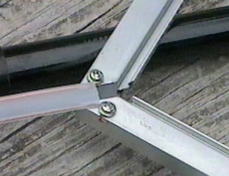
The insulator,
my only fabricated part.
Insulator was made from dense plastic, cut as a snug inset.
It maintains a 1/4" gap between the bottom two spars,
as well as, providing some material for the sheet metal
screw to bite into. The insulator insert extends 1 1/2"
into each spar for limited structural stiffness. It
is shaped
like a thick "V" and was quick to produce with hand tools.
At the loop apex, a top cover piece from of a ball-point pen was
used
to hang the diamond shaped loop. The metal clip on the ball-point
pen
piece was bent back up, forming a "U". Then the top corner
of the
diamond loop was hung in the "U". The ball-point pen piece
was
chosen for a snug fit over the fishing pole's 2nd extension.
The smallest
diameter extension is not used, it rests within the 2nd extension.
If you try one, let me (or QRP-L) know what you find.
Follow up: May 26 1999
Same idea, but bigger (75" per side).
Elevation plots in dBi.
Red are 7.04 Mhz plots separated by 90
degrees azimuth.
Blue are 14.04 Mhz plots separated by 90 degrees azimuth.
This is the simulated plot for 40 and 20 meter radiation from a 75"
loop with apex at 20 feet.
This loop has been modeled over typical stoney ground, but
not built yet. I have two 75" spars
and am looking for two more. Will probably add a small cross
member near the apex to strengthen
the overall structure. Need another round-tuit too.
![]()