
Installing Programit in the R/S Pro2066
by Mark - W3XL
What is Programit?
Programit is an easy to build radio/PC interface allowing programming the memory banks of your scanner via your PC. This eliminates the tedious task of pushing the numeric buttons thousands of times by allowing the frequency information to be permanently stored in the PC and simply downloaded to the scanner. For more information visit the web site of John Montalbano at http://www.qsl.net/ka2pyj/index.html
While the current Programit software may not directly support trunking groups, I decided to install a Programit board (Parallel version) in a Radio Shack Pro 2066, the popular trunker selling for $139.00. It took a while to figure out the 5x6 keyboard matrix and early attempts to install it with all components on board failed. You can download a configuration file for the Pro2066 below.
Thanks John, for your help.
Bottom line
When constructing the Programit board for the 2066, leave out the drain resistors (R1-5) and the diodes (D1-8) as well. It doesn't need them. In fact, it won't work with them. Just install jumpers for the diodes. Same should hold true for the serial Programit board and the 2066. Make sure you install the 5 volt regulator (7805) and just tap the 12volt supply coming into the scanner. This scanner is 100% surface mount components so clean your eye glasses before you start..
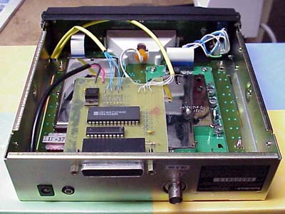
Here is the installed Parallel board. Fairly clean, huh? Don't be impressed, notice the semi-circular notch I had to cut in the far edge of the board for the speaker magnet to clear. I used a nibbler tool to cut the DB25 hole in the cabinet and I stuffed all of the spaghetti into heat shrink tubing to keep it neat. The red power line is soldered directly to the power jack terminal and the black ground wire is slipped under one of the mounting screws. Since the board sits over two metal RF shields make sure that you place vinyl electrical tape to the underside of the board just to be sure.
Programit concept developed by John Montalbano, et al.,
(software by John)
Here is a close-up of the keyboard connection points. The "X(0-5) lines" (blue wires) are all to the right and the "Y(0-4) Lines" (white wires) are to the left. (see the pattern below to id wires). The Pattern (oriented as shown in the picture) is:
Y3 Y2 Y4 X2 X0 X5
Y1 Y0 X3 X1 X4
The colored solder is just magic marker to try to keep me sane.

Here is the keyboard matrix diagram:
DOWNLOAD
Click below to download the Pro2066.dat configuration file for use with Programit software
Good Luck,
Mark - [email protected]
You are visitor
since 8/25/2000