Revised:
02/05/2006
Feeding
That Stack
Excerpted
from CQ Contest Magazine January 2000
As a newcomer to the growing group of stacked-array owners, I have been
doing a lot of experimenting and reading about the "how to" aspect
of installing and feeding HF arrays. The techniques described here are
not new, but I have not run across a comprehensive article on the subject.
I am sure they are out there; I just haven't found them. There is no
attempt here to cover all the possibilities, or even to say that this is the
best method. I just wanted to document my experiences for anyone who
might gain from it.
One of the considerations for a stack is height of the antennas. There
are lots of modeling programs out there that can be used to address this
issue. I selected my heights based on available supports and
experience at this station for what works for the bulk of QSOs in a contest.
On 10 meters my stack of 4/4 is at 65 45 ft. The 15 meter 5/5 stack is
at 80 over 42 ft. and the 20 meter 5/5 stack is at 132 over 73 ft. As
always, your mileage may vary.
Another consideration is how to feed the stack. I gave this part a lot
of thought. I have heard and read that feeding the beams with equal
lengths of coax is the standard method. First of all, this is only
true when you are feeding them as a stack and don't use them individually,
or if you are using one of the com
When looking at the feed system, several factors need to be considered.
In my case, I am feeding antennas which provide nominal 50 Ohm resistive
loads. When paralleling antennas of this type, the load is cut in half
and the power divided between them. For my case, I elected to use a
quarter-wave matching section of 75 Ohm cable to increase the apparent load
to 100 Ohms. Paralleling them then gets me back to 50 Ohms. More
on the mechanics of this later. In
order to select the antennas individually or feed them in parallel, some
sort of switch box is needed. There are several commercially available
units out there to do this. Some of them have other features such as
allowing the unused antenna to be fed from a spotting position, and or
eliminating the need for coaxial impedance transformation. For the
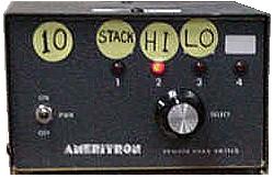
economy of my installation, I chose to modify an Ameritron RCS-4 remote
antenna switch. The modification was relatively simple and provides an
economic solution to the switching problem. It provides a basic stack,
upper, or lower antenna selection. It requires no control cable, as
relay power is coupled onto the feed line. See
subsequent notes on BIP/BOP operation.
By Dallas Carter W3PP
Updated to include Bip/Bop and 2 Relay Antenna switches
It is probably appropriate to note here that some will argue that as frequency of operation is changed, the phase between the unequal length lines will change. This is true. However, modeling of the 20 meter system described here results in about a 6 degree shift in the phase of the longer line and about a 3 degree shift in the shorter line. This results in a phase error of about 3 degrees at the high end of 20 between the two beams. Modeling the patterns shows about .01 dB change in gain and front-to-back, not significant enough for me to waste a wavelength of coax.
A note about cable prep: Velocity factor will vary slightly depending on cable quality and ageing. I always cut my cables 1-2 percent longer than the calculated length and then measure resonant length with an MFJ-259B Antenna Analyzer. Odd multiples of open-ended 1/4-wavelength sections look like a short circuit at their design frequency. To measure multiples of 1/2-wavelength sections, just place a short on the far end of the cable. This will be replicated each 1/2 wavelength. More about the cable later.
When the antennas are fed individually through the matching sections, they will look like 100 Ohms. Adding another 75 Ohm 1/4-wave section brings them back to 50 Ohms. This additional section is 14.55 ft. long. This is the basic configuration of my installations, but there are yet some specifics to be addressed: antenna feeds, cable types and RCS-4 modification.
Starting with the antenna, it is important that you pay attention to how the respective antennas are fed. They should be fed in phase. If you use Gamma matches, make sure the match is on the same side of the driven element for each beam. For Beta and T matches, you must make sure that the feed line center conductor feeds the same side of the match on each beam. For some configurations, it may be advantageous to have the beams fed out of phase due to mounting considerations or cable lengths. If this is the case, then one of the 75 Ohm phasing lines can be lengthened or shortened by 180 degrees, 1/2 wavelength. Note: If one beam is beta matched and the other is Gamma or T matched, they will also be 180 degrees out of phase. This is because a Beta match is an inductive match and Gamma and T matches are capacitive. In this case, either add or subtract a half-wave section as described above, or feed one antenna from the opposite side of the driven element.
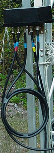
Another factor is the pigtail from the antenna feed point to the tower. These feeds must be the same electrical length. In my case, I use 50 Ohm pigtails with RF chokes from the feed point to the tower. I constructed these pigtails with the same type 50 Ohm cable, taking care that they were the same electrical length.
Now for the phasing cables. Several options are available: RG-11, RG-6, and CATV drop line. I am using a new CATV drop line product, R11-AP, produced by Omega One Communications, LLC. Note: Subsequent paragraphs relating to the use and source of R11AP have been deleted here in as much as the company is no longer in business, and the product is no longer available.
The RCS-4 basically is wired as shown in figure 1. A printed wiring board is used to make the relay interconnection and support the relays and control signal circuits (not shown). It should be noted that with no power, port 4 is active.
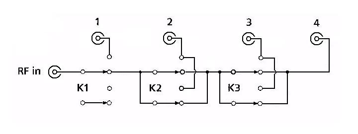
Figure 1
The board should be carefully unsoldered from the antenna connectors so that the board can be removed for modification access. Some of the jumpers on the back side of the board will be moved or removed. I cut circuits where needed, removed and moved jumpers where required. The jumpers that I added were simply short pieces of #12 insulated electrical wire. Figure 2 shows the schematic representation of the modified unit. With no power applied, there is no antenna connection.
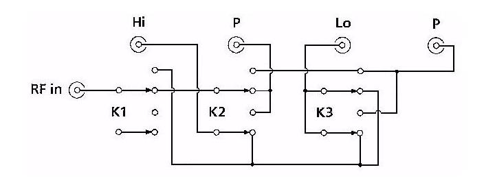
Figure 2
An electrical 1/4-wavelength cable is attached to the box between the "P" connectors. I use 50 Ohm feed line to the radio, which is attached to the "RF in" connector. The High and Low antennas are connected to the "Hi" and "Lo" connectors. When K1 is energized (Ant1), RF is applied to both antennas in parallel. When K2 is energized (Ant2), RF is applied through the 1/4-wavelength cable to the Hi antenna. When K3 (Ant3) is energized, RF is applied through the 1/4-wavelength cable to the Lo antenna.
My 20 meter beams are designed for a very flat and low SWR across the entire band. This allows me to use them on CW and SSB without the need of a tuner. I was concerned that because I built the phasing harness for CW, the reactance of the cable on the phone band would negate my broad banding efforts. I therefore found a simple fix of changing out the 1/4-wavelength section and adding a short series section with the station feed line at the switchbox. The 1/4-wavelength section is replaced with 7.5 ft. length of R-11 and a 2.5 ft section is added in series with the feed line at the remote switchbox.
Now for the reality check. When I tested the system in the CW configuration, I was pleasantly surprised to find the SWR 1.3:1 at 14350 kHz and lower on the CW end. I have therefore abandoned the need to change the cabling for SSB. I suspect that if I cut the phasing lines for 14175, the system would have an even lower SWR across the band. I mention the alternate method for those who are using commercial beams with typically narrower bandwidths. In those cases, you may find these notes of use.
Finally, I want to thank all of those who have helped in getting the stacks going here at W3PP --- specifically Jon, AA1K who does most of the climbing; along with Parris, W3PAR, and Glenn, N3HUV. Ed, N3KW, Vaughn W3IJ, Layton KE3T, and Dan N3WYN, have also given endless hours of ground support help for which I am immensely grateful. Pete, W2GJ, also deserves a big thank you for providing the R-11 drop line and his many suggestions on how to use the cable.