- |
BCD |
LPT pin |
|
CH1 |
A |
2 |
lsb |
CH2 |
B |
7 |
|
CH3 |
C |
8 |
|
CH4 |
D |
9 |
msb |
CH5 |
Latch |
see note 1 |
|
GND |
Ground |
18 |
 You can send commands to the controller board using a Terminal Emulation program. Set the program
to the COM port listed in the Device Manager. Hit the <Enter> key to get the :: prompt, which
means the unit is ready. BCD Truth table.
::CHS.OFF <Enter> = BCD 0000
::CH1.ON = BCD 1000
A 12V/1A supply and J1 at position B is required for relay operation.
::REL1.ON ::REL1.OFF
Note 1:
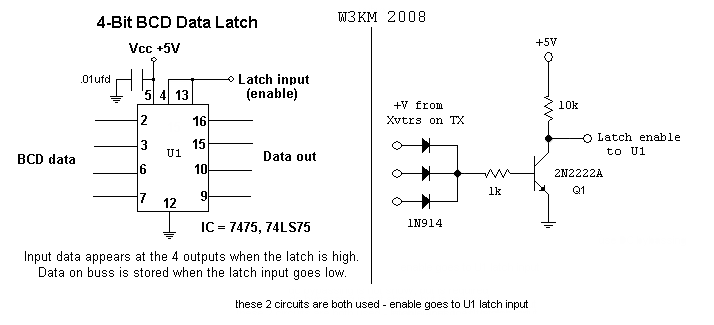
� You need the lock-out circuits below to prevent hot-switching, as explained here in #4.
� When the controller is set to a band, the BCD outputs are first cleared by setting BCD 0000. Although
unlikely, if this causes your switchbox to respond during the software write function (BCD 0000 = 6M),
connect CH5 to the `+V from Xvtrs on TX` input (with steering diode) to hold U1 enable low during the
COM port BCD write commands.
 This BCD latch circuitry can be built on perfboard with a socket for U1 and installed in the decoder
box. Both U1 and Q1 are used, Q1 latch enable output goes to U1 Latch input.
rev: 02/2016