A Switchbox for Soundcard Digital Modes
Don Wilhelm W3FPR
Nov 2007 Update - this is my first attempt at a PSK31
interface. I have made several changes over the past years and
will write up something to update this page (but it is not done
yet). The K2 firmware has been updated to include an RTTY
mode, and an independent setting for the compression was added for this
mode, so the portion of this article dealing with asuring the
compression is at 1:1 is no longer applicable.
I have spent a short time so far on PSK31. At first, I just connected a cable (with 1/8 inch plugs on both ends that I obtained from Radio Shack) from my K2 Transceiver to my computer soundcard line-in jack. This and the DigiPan and WinPSK programs enabled me to copy PSK31 signals – I adjusted my sound card input volume controls and the audio gain on my K2 so that I had a nice speckled blue background in the waterfall display, and I was seeing FB print on my computer screen.
It was not very long afterward that I wanted to transmit this PSK31 stuff too. Things got a bit more complex at that point. I had to put an attenuator in the cable from the sound card output line to my microphone. After some manipulation with values I got a respectable signal into my K2 and I could transmit this digital stuff too, but I was using manual PTT which made things a bit cumbersome going from receive to transmit.
The next step was to automate the PTT as well. The instructions in DigiPan and WinPSK showed a simple circuit – just a resistor, a diode and a transistor. I hooked it up and hid all the parts into the shell of my serial port connector with just one shielded wire going to my K2. All I had to do is tell the PSK31 program to transmit and it all happened!
After all that excitement one day, I wanted to use normal SSB – that mode which uses the microphone, and here I had all these plugs in my K2 going to my computer that needed to be unplugged. Then and there I decided that there should be an easier way, I needed a simple switch to change from one mode to another to keep my frustration level on an even keel.
I had a switch box on hand that was designed to switch serial port lines from a computer to 2 devices (or the other way around). This switch had a nice size box, a built in 9 pole 2 position switch and connectors on the back. The inside had plenty of room for me to mount everything including the microphone preamplifier.
My Grand Plan and Mods to the K2
In addition to putting all the switching into one box, I wanted to end up with only one cable connection with my K2, and also to be able to disable the speech compression of the K2 when I switched to PSK31 without thinking about changing it through the menu.
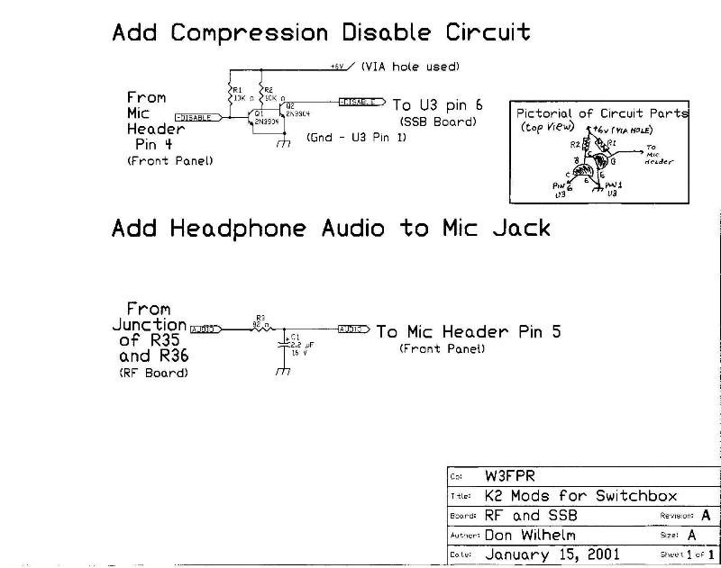
With version 2.x firmware and above, the need to use electrical circuits to disable the speech compression has been eliminated. If the RTTY mode is enabled, the K2 menu allows setting the speech compression for RTTY mode independently of SSB mode. If you chose not to enable RTTY mode, or to operate PSK31 in SSB mode instead, you may still want to use this circuit to disable the compression.
To accomplish that, I had to modify the K2 to add the headphone audio through the microphone jack and I needed yet another signal through the mic connector to disable the speech compression. Adding the headphone audio was easy – that is mainly wires, but disabling the speech compression was more challenging.
At first examination of the SSB schematic revealed that the COMP0 signal was active low which made it easy in principal – just short it to ground to disable the compression. In practice things are not that easy – I would be adding relatively long wires to ground it in my switch box, and that would likely couple noise into this line at times other than when it is grounded – some isolation was required.
I ended up with a simple circuit of 2 resistors and 2 transistors configured as a non-inverting open collector switch that I could mount on the SSB board. I was able to package them so they mounted right on top of U3 with the tops of the transistors not much higher than the adjacent electrolytic capacitors. This circuit was built with ‘flying leads’ construction to minimize the package size. All the components self support nicely and the lead lengths are very short. The result is effective control of an analog signal line at the output and a digital signal input that should have good noise immunity. If you have worked with RTL digital components, you will likely recognize the circuit.
For my new audio output, I used a 82 ohm resistor and 2.2 mf capacitor from the junction point of R35 and R36, duplicating half of the components that normally go to the stereo headphone jack. I did not want a fault in the external box to disable the normal K2 audio output. These components were added below the RF board quite near the headphone jack.
Microphone Header Configuration
My microphone header does not have any wires on it. I originally connected everything straight across using jumpers normally used in computers. My microphone wiring is identical to the wiring needed for the future Elecraft microphone. To add the signals for headphone audio and compression disable to my mic connector, I chose pins 4 and 5. Pin 5 was already unused, and I felt I could sacrifice both the UP and DOWN button functions since my microphones didn’t use these anyway. That left me with pin 3 reserved for any future needs. Your pin configuration may be different if you are using another type microphone and don’t want to alter your mic’s plug wiring.
To connect my new wires to the microphone header, I used more of the computer jumpers. Some of the jumper types have an exposed part of the metal connecting bar at the top with a small opening below that. I soldered wire to the top and plugged it onto the header using only one side. These connecting jumpers must only connect to the numbered side of the header which then connect to the mic jack. The side of the header with the signal names connects to circuits inside the K2 and should be left open for these added circuits.
Schematics of the circuits added to the K2 are shown below with pictures of my physical implementation.
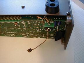
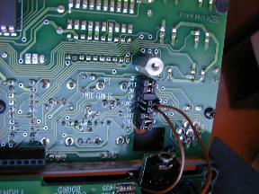
(Left Photo) Headphone Audio added (Right Photo) Header jumpers on my K2
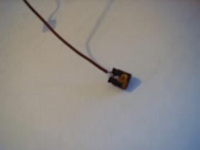
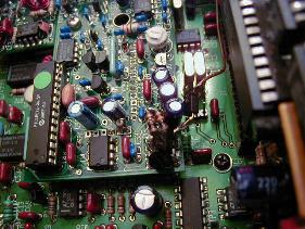
(Left Photo) Wire soldered to jumper (Right Photo) Compression Disable components added
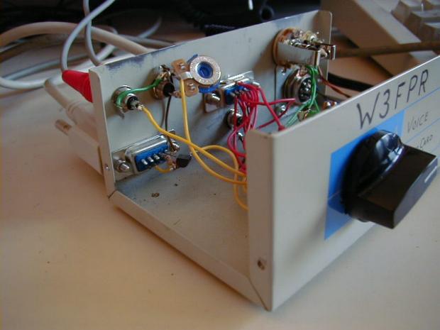
The Switchbox
This switchbox uses the components from a computer COM port switch. Only 2 of the original connectors are used and only 4 of the 9 poles of the switch. I mounted my preamplifier (details below) inside the box with its two microphone inputs (only one is shown on the schematic). I also added a jack for using an external footswitch for PTT (bonus – I can now go QLF on CW).
The headphone jack is shown in the schematic as monaural, but should actually be a stereo type with both the tip and ring wired in parallel.
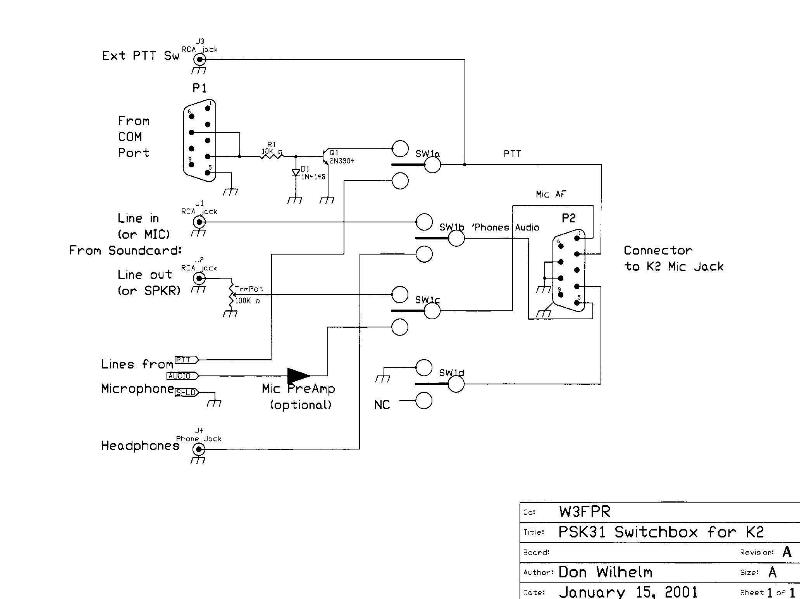
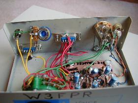
The internal wiring can be seen above. The DB9 connector in the lower left goes to the COM port and the PTT circuit is built using ‘flying leads’ construction. The RCA jacks above it are for the soundcard connections. The one with the trimpot attached is for the line out/K2 mic in signal. Adjust the trimpot for the correct audio drive to the K2 with the computer’s volume control set to midpoint or below.
The center DB9 connector is used for the cable to the K2 mic connector. I used a shielded RS232 serial cable for that task. The shield is grounded to the DB9 shell at the switchbox end and connected to my pin 8 at the K2 end. Wire this connector to correspond to your normal microphone wiring so you can use your microphone with either the switchbox or directly on your K2.
The External PTT connector is the RCA jack mounted below the center DB9.
The far end of the box contains the microphone jack (or in my case 2 microphone jacks), the headphone connector (1/4 inch type to match my Heil MicroPro) and the microphone preamp mounted on the bottom of the case. Additional photos follow.
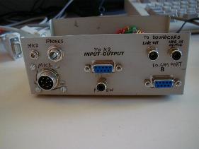
(Left Photo) Additional view inside (Right Photo) My switchbox rear panel
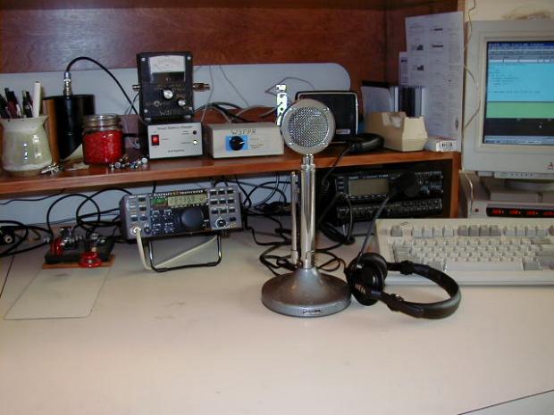
My operating position is shown above. The two microphones are in the foreground and my new PSK31 (as well as other soundcard generated digital modes) switchbox appears to the left of the D-104 microphone head. Those with sharp eyes can see another operating convenience item to the right of and behind the switchbox. I used an old sound card to extend the jacks near the operating position rather than pulling out the rear side of the computer.
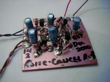
Noise Canceling with two Heil Microphones
The XYL gave me a Heil MicroPro Headset with the HC-4 cartridge for Christmas (thank you Nancy). I already had a Heil HC-5 element in my old D-104 mic frame. Both these mics needed a bit of amplification to work reliably with my K2, so I needed to build a mic preamp too. The December 2000 issue of QST came to the rescue with an article by WB9YBM and N9BRL for a Noise Canceling Microphone on page 38. This article presented a technique for using two electret mic elements to achieve a noise canceling effect. I saw it as a design that would allow me to have both microphones actively connected at the same time and possibly do double duty as a noise canceling circuit. I built the amplifier, connecting the input resistors (R1 and R10) to ground rather than the supply voltage because my Heil mic elements didn’t need any voltage on them like the original electrets do. My measurements showed that I did achieve some noise canceling characteristics even though the amount was highly dependent on the placement of the microphones. That was good because the K2 does not implement an anti-VOX and I thought that the noise canceling aspects would think the K2 speaker sound was also noise and give me some anti-VOX action too. I am happy to report success, but with the caveat that the amount is dependent on microphone placement just as I expected. The overall gain of the amplifier was unity as designed, and since I needed a bit of amplification, I changed the emitter resistors for the two output transistors (R9 and R16) from 680 ohms to 330 ohms which gave me a gain of about 2.
I built the amplifier on a piece of circuit board with land patterns cut out with a Dremel tool resulting in a pseudo Manhatten style construction. I have ordered the punch from Harbor Freight to punch out true Manhatten style pads, but it has not yet arrived. If such construction practices are counter to your ambition, a circuit board is available – please consult the original article.
One additional note – I had to add a 10 ohm series resistor and a 47 mf capacitor on the +5 volt supply lead to reduce some noise spikes that caused me some trouble when I first connected the preamp.