
Many K2 owners have expressed a strong desire to separate the K2 dot paddle input from the PTT. I have exchanged e-mail with Wayne Burdick about providing it, and he has said he would like to do it in the firmware but at this time, he has neither the space in the firmware nor the time to implement it even if the space were available.
The K2 normally shares the Dot input and the PTT input on one input line. This works great if one uses the QSK feature of the K2 on CW and uses the PTT on SSB. The problem comes from those users whose stations are set up to enable transmit with the push of a footswitch or the VHF/UHF operators who use a sequencer and delay the onset of RF so no hot switching occurs. For these operators, pressing the PTT switch while in CW causes the K2 to produce full output (or a string of dots or dashes depending on how the paddle input parameter is set in the menu).
Additionally, some operators just like to use PTT for CW to avoid hearing the relay click in their amplifiers. Whatever your reason for wanting a separate PTT input on CW, I have a solution that you may want to implement.
Out of curiosity, I wanted to see if I could come up with something to provide the PTT input in hardware. After a few trials, I thought it best to restrict myself to one DIP because the space inside a fully loaded K2/100 is too cramped to allow the addition of anything physically large. Surface mount is an unacceptable solution because not everyone would be capable of building even a simple logic addition with surface mount devices. After scouring through the truth tables of several logic chips, I discovered that the 74AC153 Dual 4-Input Multiplexer could do the job.
The 74AC153 is a dual 4 input multiplexer which can select 2 output bits of data depending on the states of two common select lines. In other words, this chip works like a 2 pole 4 position switch and the select lines represent the position of the switch. In my implementation, the TXC line from the SSB board is isolated and inverted then used as the input to one of the select lines while the other select line is used for the added PTT input. The original dot and dash lines are applied to the data bit 0 inputs, and the new PTT input is also fed to the data bit 1 input of the multiplexer which provides the dot output. The other data input lines are normally tied at a logic high level. A manual switch is included to add the data inputs that are normally high in parallel with the dot and dash input lines restoring the function of the original K2 QSK should that be desirable.
| State | Select 1
(+SSB) |
Select 2
(-PTT in) |
Enable
(tied low) |
Data 0
(dot or dash in) |
Data 1
(-PTT on dot side only) |
Data 2 | Data 3 | Output
(Dot or Dash out) |
| 1 | Don't care | Don't care | High | Don't care | Don't care | Don't care | Don't care | Low |
| 2 | Low | Low | Low | Low | Don't care | Don't care | Don't care | Low |
| 3 | Low | Low | Low | High | Don't care | Don't care | Don't care | High |
| 4 | High | Low | Low | Don't care | Low | Don't care | Don't care | Low |
| 5 | High | Low | Low | Don't care | High | Don't care | Don't care | High |
| 6 | Low | High | Low | Don't care | Don't care | Low | Don't care | Low |
| 7 | Low | High | Low | Don't care | Don't care | High | Don't care | High |
| 8 | High | High | Low | Don't care | Don't care | Don't care | Low | Low |
| 9 | High | High | Low | Don't care | Don't care | Don't care | High | High |
The Truth Table for the 74AC153 is shown above.
State 1 cannot occur because this input is connected to ground and is always at a Low state.
In CW mode, the Select 1 (+SSB) input is always low and with the
PTT input high (inactive), the logic will be in State 7 because the Data 2 input
is tied high.
The output will not change from this state until the PTT input goes Low.
Once the PTT input is Low, the state will toggle from 3 to 2 depending on
whether the paddle line is open or closed.
When the K2 is placed in SSB mode, the idle state will be 9, but once the PTT input is made active low, the state changes to 4. The -PTT input line is also tied to the Data 1 input of the multiplexer (on the dot side only) to allow the output to go Low (state 4 instead of state 5) which activates the K2 internal -DOT/PTT signal to the microprocessor and enables transmit mode. This addition (-PTT connected to Data 1) is not needed on the DASH side because the K2 microprocessor ignores the DASH input when in SSB mode.
If you look ahead at the schematic, you can see that I included a DPST switch where one pole ties the Dot input to the Data 2 and Data 3 inputs and the other pole ties the Dash input to Data 1, 2 and 3 inputs. If this switch is closed, and CW mode is set, the idle state is still State 7. Activating PTT changes to state 3 if the paddle input is open or State 2 if the paddle line is closed. But since the paddle input also appears on the Data 2 input, the output will follow the paddle input line without activating the PTT input, so closing the paddle can switch to State 6 if the PTT input is high or switch to State 2 when the PTT input is low. Note that only activating the PTT alone will not cause the K2 to begin transmitting. The K2 will operate in its normal QSK mode, but if you have a footswitch attached, it will no longer work for QLF operation.
In SSB mode with the switch closed, State 9 is the idle state until the paddle line is closed and then State 8 is presented, but if the PTT switch is closed, State 4 becomes active and in either case, the output goes low. This is an advantage if one uses an external footswitch for CW, the same footswitch will work for SSB PTT.
My implementation does not meet the Elecraft 'elegance' criteria because I found no way to avoid using wires to connect the circuit board to the K2, and I am not really pleased with running a 'flying wire' from the SSB board, but the circuit does work to provide a separate PTT input for the K2. I have included some considerations for placement and operation at the end of this article, please review them before deciding on your final implementation because these decisions will influence your choice of parts for the jacks, connectors, and the switch.
Parts List:
1 - 74AC153PC logic IC - 16 pin dual 4-input multiplexer - Mouser 512-74AC153PC
1 - 2N7000 N-channel enhancement mode MOSFET - Mouser 689-2N7000
1 - 1N4148 diode (Mouser 78-1N4148)
6 - 2.2k 1/4 watt 5% resistors - Mouser 291-2.2K (minimum order of 10)
*1 - DPST switch (or DPDT with one side unused) - Mouser 10TA860 or 10TA815
*1 - input jack for new PTT input (RCA type) - Mouser 16PJ052 or 161-1052
* Connector (plug and jack pairs) for disconnecting wires to the K2 RF board and SSB option - 10 conductors total. I suggest installing 11 pins of AMPMODU breakaway header stock (Mouser 571-21032390) on the PC board and using a 9 pin AMPMODU cable connector (Mouser 571-1874995) with one pin blanked for keying purposes for the connections to the RF board and a one pin connector (Mouser 571-7874992) for the connection to the SSB option board. If you chose the connectors I have specified, you will need 1 keying plug (Mouser 571-870772) and 10 receptacle contacts (Mouser 571-876673). Other connector options are usable as well (even direct wiring will do, but repeatative removal may prove tedious).
*1 - PC board for mounting - perfboard material or similar - Radio Shack 276-150A cut in half will do if nothing else suitable is available.
* Double sided foam tape for mounting the assembled circuit board - look in craft stores or Home Depot or Lowes hardware departments.
The items marked with an asterisk (*) above are suggestions and will depend on your chosen mounting location for the circuit board, PTT jack and switch.
Assemble the circuit board as indicated in the schematic above.
Use connectors to enable the added board to be removed from the K2. The type of connectors and where they will be placed depends on your choice of location for the circuit board
Add the 2N7000 MOSFET to the bottom of the SSB option board
Remove the SSB option board from the K2 and turn the solder side up
Place the 2N7000 on the board with the flat side facing up (away from the board)
Form the gate lead (center) so it will contact the SSB board.
Solder the gate lead to pin 12 of U1 (see photos below).
Form the source lead to reach the center pin of resonator Z1 (this is a ground location).
Connect a wire (long enough to reach to your chosen circuit board location) to the 2N7000 drain.
Replace the SSB option board
Remove the left side panel from the K2 (this provides access to the R1 and R2 locations without removing the heat sink).
Remove R1 and R2 from the K2 RF board.
Connect the -DOT IN wire to the solder pad for R1 that is closest to the rear panel
Connect the -DOT OUT wire to the remaining solder pad for R1
Connect the -DASH IN wire to the solder pad for R2 that is closest to the front panel
Connect the -DASH OUT wire to the remaining solder pad for R2
Connect 2 wires to S1A.
Connect 2 wires to S1B
Connect the -PTT IN wire to your PTT input jack (the return side of the jack must be grounded)
Connect the wire added to the SSB option in the 2nd step above to the +SSB input of the new circuit board.
5 volt and ground supply connections are available on K2 RF board connector P1
Remove the K2 front panel board (the control board may also be removed to provide easier access).
Note that the wires to be connected must be routed above the K2 power switch - be certain they are long enough.
Connect the +5V wire to pin 18 of P1
Connect the GROUND wire to pin 20 of P1
Reassemble the front panel and left side panel
Decide where the new circuit board should be mounted
Mount the circuit board with double sided tape
Place 2 layers of foam tape on the solder side of the circuit board
Put it in your chosen location.
Press the board down firmly.
You should consider the consequences of pressing the PTT switch on your microphone because this PTT line still behaves as it always did. If that situation can damage your equipment, you will want to remove the PTT jumper from the microphone configuration header so only the new PTT input will function.
There are several places you may want to consider for mounting this new PC board. One choice is inside the top cover where you can use the existing transverter holes for your new PTT input jack and the switch shown in the schematic. That location will allow you to permanently wire the switch and PTT input lines directly to the circuit board (they will rarely need to be removed). The parts list includes a switch and jack that can be mounted in these transverter holes (even though the holes are somewhat oversize), your removable connector requirements will be reduced from that indicated in the parts list.
The switch (S1) referred to is optional, and can be eliminated if mounting is a problem. The switch restores QSK CW operation to the K2 when closed. If you do eliminate the switch, make no connections to the circuit board where the switch is shown.
Another choice is to mount the circuit board on the left side panel just above relay K13. This location allows clearance for the RTC battery on the KAF2 or KDSP2 options, permits a short wiring path for the DOT and DASH input and output lines, and permits mounting the new PTT input jack on the rear panel near the key jack. You will have to drill a hole in the rear panel 3/4 inch in from the side panel and no more than 1/2 inch below the top edge of the panel - the fit is tight. See my photos for the location of the jack. If you chose the side panel mounting, the RX ANT location can be used for the switch if that is available, but if you have the 160 meter option installed and the K60XV too, there is no room on the lower rear panel to mount anything else - in that case, consider mounting the switch in the top cover and using a connector to disconnect the switch wires.
If you have the KPA100 installed, there appears to be little choice for mounting other than the left side panel, and if you have the 160RX and K60XV options installed, there is no room for the switch anywhere on the rear panel. You may want to consider mounting the switch on the side panel (that means drilling holes in the side panel), and perhaps a small slide switch would be a better choice than the toggle switch specified. It would also be possible to simply run the switch wires out the back between the rear panel and the KPA100 and mount the switch on a bracket outside the K2. Consider the best mounting for your situation.
There is one more possibility for the PTT input that I have considered, and that would be to use the PTT input from the microphone jack. To use the mic PTT as the new PTT input, disconnect the PTT jumper from the K2 microphone configuration header and wire the header pin that is connected to your microphone's PTT line to the PTT input on the new circuit board. You will then have to figure out how to make your microphone PTT switch initiate your sequencer or external relay - this will likely require some kind of adapter on your microphone connection. The exact wiring will depend on your particular microphone and your switching arrangement in the shack.
If switch S1 is placed in the open position, the behavior of the K2 will be changed. No longer will hitting the key begin transmit, the PTT input must occur before any RF is generated. This is true whether in CW or SSB mode. The PTT line at the microphone jack will behave as it always did before unless you have removed the jumper from the mic configuration header. In SSB mode, the new PTT input will put the K2 into transmit, but the DOT paddle will no longer cause the K2 to go to transmit mode as it did before.
With switch S1 in the closed position, normal K2 QSK for CW is restored with one added plus, the new PTT input will also function as a true SSB PTT input, so if you are now using a footswitch for CW PTT, that same connection will now work for SSB regardless of the position of S1 - and the footswitch will no longer produce RF when in CW mode.
If you are using a footswitch or sequencer output, connect its output to your new PTT input. This should be a simple contact closure to ground and should be isolated form other control circuits you may have in your station. I have included a protection diode in the PTT line to protect against the possibility that there may be an open circuit voltage greater than 5 volts on your PTT line, but do measure the open circuit voltage on the line before connecting it - if there is voltage on it, consider using a different set of contacts. The closed circuit voltage on the PTT line should go lower than 0.5 volts if the circuit is to switch reliably - the current is only about 3 ma. and a resistance of more than 150 ohms when the PTT contacts are closed is certain to cause problems.

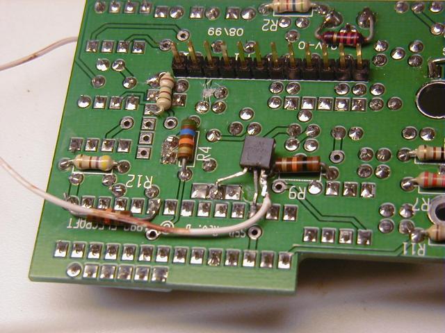
My prototype board and 'flying wire' connections

Detail of R1 and R2 removal and new wires added
(I just lifted one end of R1 & R2)
2N7000 MOSFET added to SSB option to bring out +SSB signal

Ground and +5 volt wires added (note the wire routing under the Control Board)