|
| Using a SmartCharger
with the K2 Internal Battery |
I had
been using my K2 with the internal battery option for about a year, and
had tried several power supplies with it, and I found that those I
could adjust to an output of 14.4 volts were capable of keeping my
internal battery charged in normal use. While these power
supplies placed 13.8 volts at the battery terminals (float voltage for
a 12 volt SLA battery), after a discharge cycle, it would take a long
time (several days) at the float level to fully recharge the battery.
My
research into the care and feeding of SLA batteries indicated that the
most common mode of battery failure was as a result of undercharging.
Not wanting to sacrifice my battery's life, I decided to invest
in a SmartCharger to keep the charge topped off. There are
several on the market, but I chose the kit by A&A Engineering for
the purpose. This is a 3 stage charger available assembled in 1
amp and 2 amp versions, or a kit which is programmable for ½ amp
or 1 amp output with the parts supplied, but can be changed to any
current rating by changing one sensing resistor.
I
chose to set my charger to 250 ma to prevent overcharging the battery
during periods when my K2 was turned on and the battery was already
charged. During receive my K2 draws approximately 250 ma, so when
the SmartCharger switches into bulk charge mode (the charger sees only
a current draw with the K2 on, and thinks the battery needs to be
charged), the K2 takes all the current the SmartCharger can supply and
no current flows into the battery. Naturally, during transmit
periods the battery will become discharged, but will be recharged after
the K2 is turned off. If your operating periods are normally long
compared to the time your K2 is turned off you may want to set your
charger for ½ amp. The potential for damaging the battery
with only 250 ma of current during times when your K2 is turned on is
quite small (according to the battery manufacturer's information).
Using
a SmartCharger requires a direct connection to the internal battery,
but the K2 uses a protection diode as well as the resetable fuse in the
power connector path. I wanted a fused direct connection to the
battery with a connector on the rear panel. I found the space
cramped since I already had the KAT2 installed in addition to the
internal battery and I did not want to sacrifice the existing holes for
the transverter option. The figures show how I fit it all into
the top cover.
I
bought only 4 parts:
Inline
Fuse Holder - RS 270-1238c or Mouser 44FH498
Fuse -
5x20mm, 2 Amp Fast-Acting - RS 270-1052 or Mouser 44FM052
Coaxial
DC Power Jack - 5.5mm OD x 2.1mm ID - 21/64" hole - RS 274-1582
or Mouser 163-4304
Coaxial
DC Power Plug - 5.5mm OD x 2.1mm ID - RS 274-1569A or Mouser 1710-2111
Tie-Wraps
or suitable substitute and a 10 inch length of #16 wire are also needed.
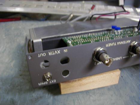
The
first step was to drill the hole in the top cover. My choice for
this hole was next to the External Speaker jack. I first used a
Post-it note to shield the KAT2 from any metal chips that may be
produced, drilled a pilot hole and finished with a 21/64 inch drill
bit. The outside of the hole was de-burred with a larger size
drill, and a utility knife de-burred the inside. I could have
removed everything from the top cover for this drilling procedure, but
I took the `lazy' way out.


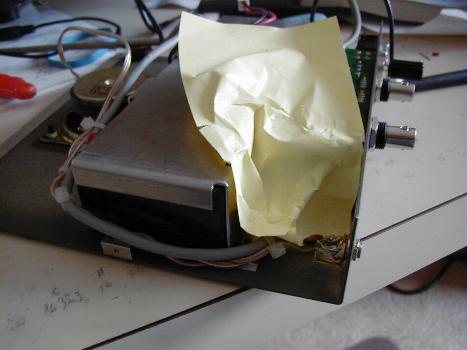
Chip
Protection Shield
The
new connector hole
(Click the photos for a bigger image)
Disconnect
both Faston connectors from the battery terminals and cover the battery
terminals with tape to prevent any accidental shorts.
The
next step is to mount the connector. Orient the connector so you
can solder to the terminals. The third terminal for the internal
switch is not used.
The
leads on the inline fuseholder were just long enough to solder one end
to the connector center pin and to place the body of the fuseholder
around the corner of the battery. Be certain that there is enough
slack to allow separating the fuseholder for fuse replacement.
The other end of the fuseholder is soldered to the Faston
connector at the positive terminal of the battery. I was
successful in re-using the original Faston connectors for the battery
(with the help of some shrink tubing), but you may want to use new ones
- it will be easier.
Solder
a #16 wire to the shell side of the new connector and dress it around
the end of the battery. Solder the other end of this wire to the
Faston connector at the negative side of the battery. Be sure
there is enough slack to get the Faston on and off the battery terminal.
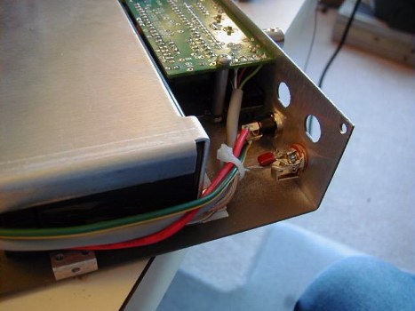
Dress
the wires in place and secure to the other wiring with Tie-Wraps or
other suitable devices. Place the terminals on the battery and
you are ready to roll. Put the K2 top cover back on. The
photos below show what mine looks like.


Wire
dressing
New
connector wiring
(Click
the pictures to see a larger image)
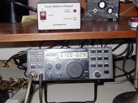
My K2
with the A&A SmartCharger
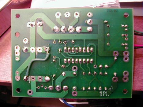
Modifying
the A&A SmartCharger for 250 ma. bulk current.
Nov
2007 Update - A&A Engineering is now offering a switchable model
which can be wired for 250 ma. Contact A&A Engineering for
more information.
The A&A Engineering charger kit is supplied with two 0.5 ohm
resistors which will control the bulk current. The stock
instructions tell you to install one at position DS1 for ½ amp
out and install the second one at DS2 for 1 amp output (DS1, DS2, DS3
and DS4 positions are connected in parallel). To obtain my
desired 250 ma. output I needed a 1 ohm resistance. A careful
examination of the circuit board told me that if I made 2 cuts and
added one wire I could connect the two 0.5 ohm resistors in series and
have my 1 ohm total resistance. As a bonus, adding a switch
across one of the resistors to short it out would allow switching the
charger from 250 ma. to ½ amp bulk current - solder pads are
available. The cuts and the added wire are shown on the left side
of the photo below.

Click
to enlarge
The
cut near the center left of the board is just on the right side of the
thick vertical trace and the second cut is just to the left of the
lower thick vertical trace . Install one of the 0.5 ohm resistors
in position DS1 and the other in position DS4 and add the wire as shown
to connect the two ends of the resistors that were isolated by the cuts
- this places the two resistors in series.
If you
wish to add the switch to change the bulk current the wires to the
switch would be connected to the pads normally occupied by DS2.
The bulk current will be 250 ma with the switch open and 500 ma
with the switch closed.
There are several SmartChargers that can be used. For those who want to
use the A & A unit as I did, you may obtain it from,
A & A Engineering
2521 W. LaPalma, Unit K
Anaheim, CA 92801 USA
Ph (714) 952-2114 Fax: (714) 952-3280
E-mail: [email protected]
The A & A Engineering website is at:
http//:www.a-aengineering.com/
The 1 amp charger kit has parts and instructions for both 1 amp and 1/2
amp rating. The assembled version comes only in the 1 amp rating. They
also have a 5 amp (assembled only) charger available if you have need
for a higher capacity charger.
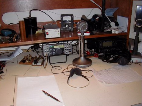
My K2
operating position