Fixed Audio
Output for the K2
I have had several requests to provide a fixed audio output from the K2. After looking at the circuits that others have designed, I found that they used single ended audio input and were usually incorporated with some other circuits that were not useful to me. I already have my external Digital Modes Switchbox built to automate digital transmissions, but I still lacked the fixed audio that would allow me to position the K2 audio gain anywhere without disturbing the gain settings on my soundcard.
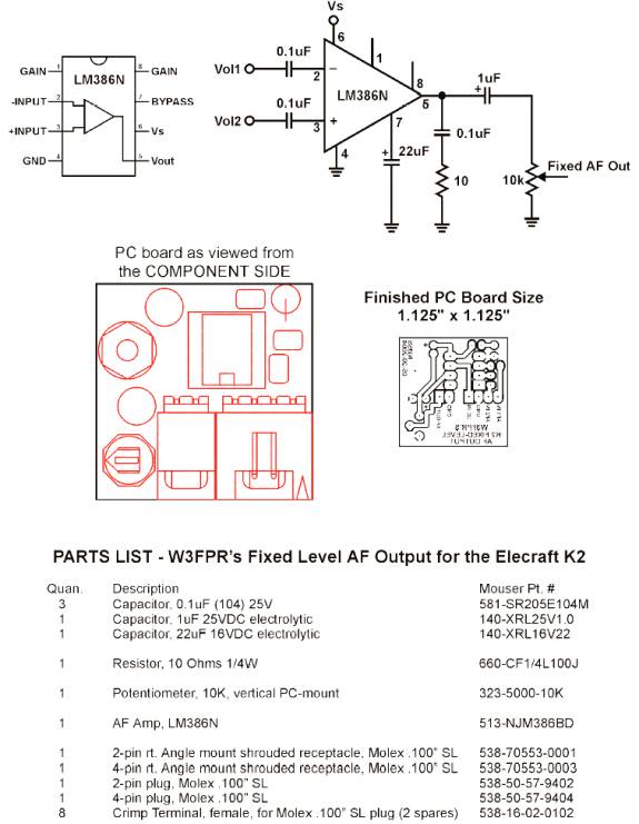
I choose a LM386N-3 Audio Amplifier IC for its differential inputs, high available gain, small packaging, and low external parts count. The –3 version works well from the 8 volt supply in the K2. It seems not widely known that the LM386 works just fine into a high impedance loads as well as low impedance. The amplifier is directly specified for voltage gain (Av) which then gives rise to the power available once the load resistance is known. The power available increases as the resistance decreases (P = V2/R) but the voltage is independent of the load.
After building a couple of prototypes successfully on perfboard, I talked with Tom Hammond N0SS at Dayton 2004 and Tom generously offered to lay out a small PC board for this application. Tom did more than just do the PC board layout, he made up a nice documentation sheet with the schematic and parts list, provided some sample boards for evaluation, and provided the negative layout to FAR circuits for final board production – then he even volunteered to shear the panels of boards for me too, I owe Tom a lot for his help on this project – without his assistance, the etched PC board would not have been possible.
I no longer have kits nor boards for this project. The circuit is
simple enough that it can be
easily handwired on a small piece of perfboard, or even built Manhatten
style.
This Fixed Audio Output should serve the needs of those who want fixed audio for digital modes as well as those who would like to drive a tape recorder or other audio device.
The following pages provide instructions for assembling and mounting my full kit.
The schematic, parts list and board layout are shown below (compliments of Tom Hammond).
Assembly Instructions
- Insert the components into the circuit board and solder. Clip all leads as close to the board surface as possible (use flush cutters if available)
- The plastic locking bar on the top, front of the board mounted (male) connector is not needed in this application and should be removed to reduce the force required to remove the mating female connector. Clip this bar off with diagonal cutters. The keying function of the connector is retained even though the locking bar is removed.
- Drill a 15/64 inch hole in the rear panel for the RCA jack. This hole should be centered no more than 5/16 below the upper edge of the panel and ¾ inch from the left edge (near the key jack). The clearances are close – use care and be certain the jack will clear the 40 meter bandpass filter inductor located nearby.
- De-burr the hole for the jack.
- Mount the RCA phone jack with its soldering lug. Orient the solder lug toward the left side panel.
- Cut 2 - 1 inch squares from double sided foam tape.
- Place one square of the foam tape on the solder side of the PC board and remove the protective paper
- Place a second layer of foam tape over the first making a double layer.
- See the KPA100 Mounting Note at the end of this document if you are mounting this board in a K2/100.
- Position the PC board on the left side panel centered above relay K13 and as close to the RF board as possible without interference. Press the board firmly to be certain the foam tape adheres securely.
- Separate the flat cable into a 4-conductor cable and a 2-conductor cable.
- Mark one edge of each cable all along its length to identify conductor #1. A permanent “Sharpie” marking pen does an excellent job.
- At one end of each cable, strip 1/8 inch of insulation and tin the wires.
- Solder each conductor to a Molex female SL plug terminal. Be careful not to get excess solder onto the outside of the terminal. Only a small amount of solder is required.
- Insert the terminals into the housings. Place the keying tab of the housing up and with the cable to be inserted on the left side, the marked edge of the cable will be inserted into the edge away from you.
o If you are uncertain of the cable orientation, check with the markings on the PC board. The marked conductor #1 of the 2 conductor cable will mate with the AF OUT pin and conductor #1 of the 4 conductor cable will mate with the DC IN pin.
o You will have to separate the conductors for about ½ inch back to insert the terminals into the housing.
- Cut the 2 conductor cable to a length of 7 inches (including the housing). Separate the conductors about ½ inch, strip 1/8 inch and tin the wires.
- Solder the marked conductor #1 of the 2 conductor cable to the center terminal of the RCA jack.
- Solder the remaining conductor to the solder lug of the RCA jack.
- Cut the 4 conductor cable to 10 ¾ inches (including the housing).
- Separate the 4 conductors into two pairs for a distance of 2 5/8 inches.
- Cut 2 3/8 inches from the pair that is unmarked (conductors 3 and 4). Strip 1/8 inch of insulation from each conductor and tin.
- Remove the Control Board from the K2 and place it solder side up and the edge containing the pins that connect to the RF board closest to you.
- Locate P2 pin 5 (+8 volts) and solder the marked conductor #1 to it.
- Locate P2 pin 7 (ground) and solder conductor #2 to it.
- Locate P3 pin 1 and solder conductor #3 to it (VOL1).
- Locate P3 pin 2 and solder conductor #4 to it (VOL2).
- Where the cable exits the left edge of the Control Board, bend the cable sharply so it exits toward the component side of the board. Place a piece of electrical tape across the cable near the edge of the board to keep the cable in place.
- Replace the control board in the K2. The side to side fit will be a bit tighter than before because of the thickness of the cable, so use appropriate care. Be certain the added cable exits close to the RF board to allow clearance for the KDSP2 option if installed. You may put a few creased folds in the cable so it remains in place and will plug into the new fixed audio board.
- Plug both cables into the fixed audio board. Position the 2 conductor cable to the output jack close to the RF board to allow clearance for the KPA100 or internal battery option.
- Turn the K2 on and tune to a suitable signal.
- Set the 10k potentiometer on the fixed audio board for a level suitable to drive your external audio equipment. Up to 3 volts p-p (1 volt rms) with a 50 microvolt signal applied to the antenna input is the normal output available.
Photos
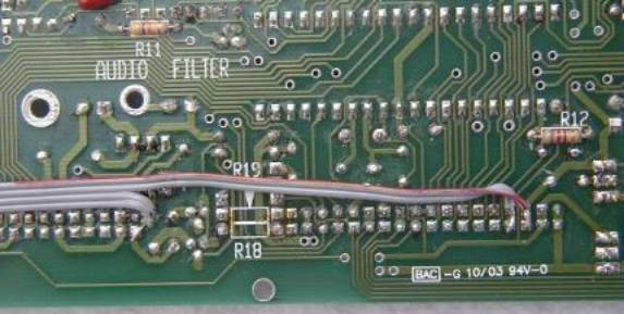
Connections to the control board
Routing and securing cable onto the control board
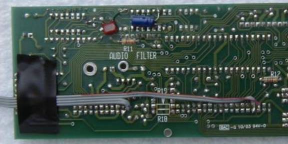
Installed Fixed Audio Board showing cable routing close to the RF Board.
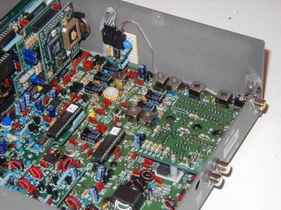
Installing between the Front Panel Board and the Control Board
I have added a PDF document which shows how I mounted the board between the K2 Front Panel and Control Board, and is now my recommended mounting method even though the components must be laid flat. If you have level controls in your external device, the variable pot can be replaced by a couple of fixed resistors. Since this mounting may use short connecting leads, the connectors (the most expensive parts) may be eliminated since all but the output wires are contained entirely on the K2 Control Board. Right click this link to download or left click to view here FP-CB mounting
NOTES for mounting in a K2/100
The side-panel mounting position becomes quite critical in the K2/100 with the upgraded shield and its speaker shield. It depends on how the speaker shield cap was positioned.
To determine if you can use the side panel mounting, assemble the K2/100 and remove the left side panel. Test fit the fixed audio board to see if it projects above the plane where the inner surface of the side panel will be (use a straightedge from top to bottom). You may have to position RF Board C60 a bit away from the edge, and place the Fixed Audio board so it overlaps the C60 position.
Measure the position VERY carefully and place the board on the side panel, or you might be successful if you remove the paper from the foam tape and lay the side panel in place (move it straight downward with no side movement) – if the board sticks to the panel it will be in the correct place, if it doesn’t stick, you will have to measure the position carefully and translate the mounting position onto the side panel. Measure to the nearest 1/32 inch (1 mm) and “measure twice, stick once”.
Should you find inadequate room to mount it on the side panel, you can use an alternate mounting location near the center of the RF board. Remove the KPA100 and locate the IOC chip – it is the one in a socket located to the left rear of the SSB option board. Remove only a portion of the paper from the foam tape and stick the Fixed Audio Board onto the top of the IOC chip.