I wanted to keep the installation as simple as possible. No massive slabs of concrete in the back yard and no tower climbing. During Field Day 2000, our local radio club, the Carroll County Amateur Radio Club, setup an AB-577. Several of my amateur friends were also using the AB-577. After seeing how easy it was to erect one of these masts during Field Day, I realized this was the way I wanted to go.
After planning this project, I settled on the following configuration:
- AB-577 mast (height 55 feet)
- 2 element quad manufactured by Lightning Bolt
- Single feed line with all driven elements tied together
-
Ham II rotator
The Ham II rotator is rated for 10 sq. ft. of wind load when mounted inside a tower. The Lightning Bolt quad has a wind surface area of 6 sq ft. My installation requires that it be mast mounted which lowers the effective wind load capacity of the rotator. To minimize the load on the rotator, I put most of the mast below the rotator with about a foot of mast above the rotator. The completed configuration results in the boom being 58 feet above ground with 3 feet of mast off the top adapter of the AB-577.
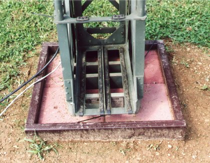
Below are some pictures of the installation. The first two photos
are of the antenna base. The AB-577 sits on a small (2 ft by 2 ft)
concrete slab constructed of 1 x 1 foot patio blocks. The blocks
are held in place with a wood frame constructed of 2 x 4s and weather proofed
with about 8 coats of polyurethane.
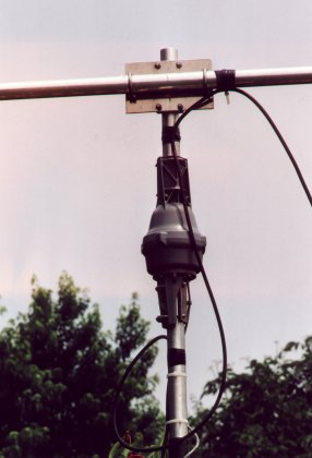
The Ham II rotator is mounted on top of 30 inches of 2 inch O.D. thick
wall alluminum mast. I had approximately 12 inches of the mast turned
down to fit inside the AB-577 top mast adapter. The mast is held
in place with a bolt through the mast and mast adapter.
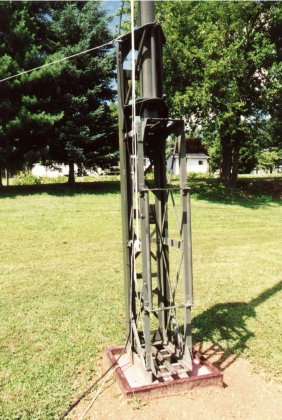
The AB-577 is guyed in three places, at the 55, 30, and 8 foot level. My guying system is a hybrid. I am using philystran (non-conductive) guy wire on the top guys to minimize any antenna pattern distortion caused by the close proximity of the upper guys with the quad's elements. I purchased extra clamps and tubes for the AB-577 so I could take the antenna above 50 feet. I chose to go to 55 feet to insure that I had sufficient clearance between upper guys and 20 meter loops. For an increased safety margin on the guys, I use turnbuckles on the critical guy wires - the upper and lower guys. I made this decision after one of the provided guy wire tensioners (the large green device on the middle guy wire in the picture below) failed while I was doing a dry run of the mast raising procedure.
To insure that I had a solid guying system, I chose not to use the provided
3 foot screw-in guy anchors. Instead, I purchased heavy duty 4 foot
drive-in guy anchors outfitted with guy wire mounting plates. These
can be seen in the lower right portion of the picture below.

After assembling the antenna and mounting it on the mast, I attempted to make adjustments to the quad's reflector tuning stubs for maximum front-to-back. I found that the recommended stub lengths worked just fine. When assembling the Lightning Bolt quad, following the directions carefully will pay big dividends. The VSWR and front-to-back is good on all bands. I did not have to change any of the element lengths. The lengths given in the instructions were right on the money. The VSWR is well below 2:1 on all bands varying between 1.3 to 1.6 on 20 thru 10 meters. The VSWR does not reach 2:1 anywhere except on the upper end of 10 meters above 29.000 MHz.
I built the antenna per Lightning Bolt's recommendaion which uses a single feedline with all 5 of the driven elements tied together and fed with a 2:1 current balun. When planning this project I seriously considered feeding all of the bands separately using a remote coax switch. Before purchasing the antenna, I made several contacts with other hams using the antenna and they all told me that the recommended configuration worked well and that if you followed the assembly instructions no tuning would be necessary. Well... they were right. Feeding all five driven elements in parallel is a compromise, but the hit in performance appears to me fairly small from my experiences with the antenna so far.
The antenna elements were assembled on the ground. The boom was then mounted to the boom-to-mast plate and the elements were attached to each end of the boom. This process proved to be a challenge. With the help of my son Danny, we were able to attach the elements from a step ladder. Due to interference from the lowest set of guy wires which are only 8 feet above ground level, several of the outer loops on one of the elements had to be loosened to clear the guy wires. Danny came up with the process of lossening the loops on one element, mounting the other element, raising the element a few feet with the AB-577s winch, then re-tightening the loops. The entire process was completed with a six foot step ladder. Without it, mounting the antenna would have been a much more difficult process.
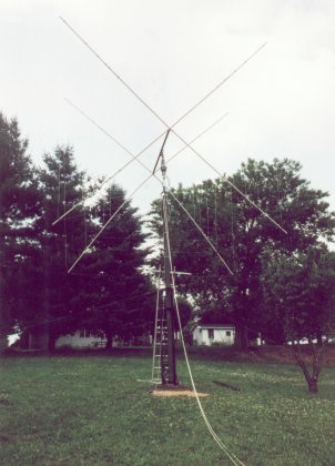
The photo below is of the completed antenna before being raised to its final height. While trying to adjust the reflector stubs, I used the antenna at a height of 25 feet for several days. It out performed my dipole at 35 feet by a large margin even at this 'low' height.
After adjusting the reflector loops, the antenna was rased to its final
height of 58 feet with the help of my son Danny and my brother George who
is also a ham - N3DRX.
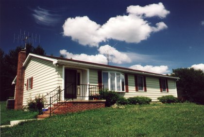
The photo below is of the QTH. If you look closely you can see
the quad above the roof. The base of the antenna sits about 80 feet
from the back of the house. The antenna on the chimney of the house
is a pair of vertically polarized 6 element yagis for 2 meter FM.
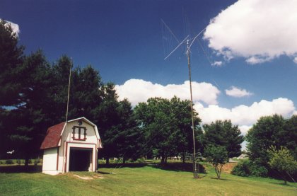
Below is a photo of the back yard. The shed houses my utility
tractor and other lawn equipment and serves as the support for a 35 foot
mast which holds my mult-band dipole. The quad sits above the tree
line along the back yard.
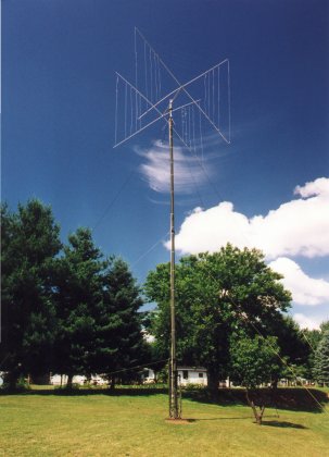
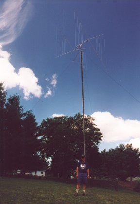
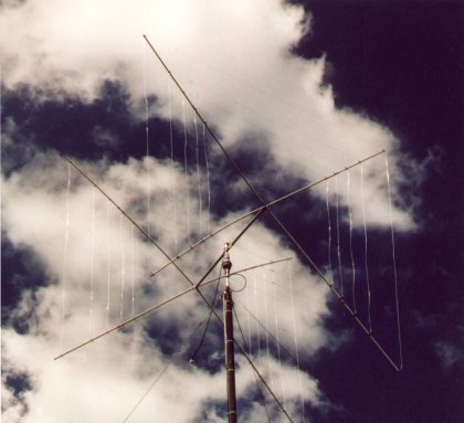
The remaining photos are of the quad taken from varoius perspectives.
That's me with the AB-577 and quad growing out of my head.
A closer view and one looking straight up the mast. The lowest
guy wires can be seen near the bottom of the photo.
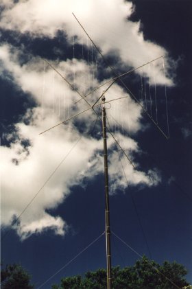

The finished product - a work of art.
The first 5 days after completing the antenna installation, I worked six new countries (XW0, A92, T5, 9V1, P29, and 9Q5) all with 100 watts. Now, when I call CQ, I get calls from interesting places such as 9N7, VU2, BD0, HL1, DU1, 5B4, VK, ZL, KH6, and UA0.
| Home |