Gates
Radio M-5078 Commercial SW AM/CW
Transmitter
Restoration Details
By John
LeVasseur, W2WDX
Copyright March 05, 2012
Gates Radio M-5078 Commercial SW AM/CW Transmitter
Restoration Details - Part Three
Additional Information About this Transmitter
Prior Modifications
Before I go on any further on the restorations process, I would like to talk about some of the modifications that were performed prior to me taking possession of this transmitter.
- PTT Relay
As I had mentioned earlier in Part I, the factory PTT scheme in this transmitter is limited. The microphone switch is only used to make or break the audio chain in the microphone itself. It has no function in controlling relays. The radio is switched from receive and transmit and back again via the plate power switch on the PS/modulator unit.
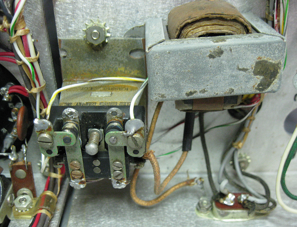
A modification was added to this. A transformer and additional relay was added and a different mic plug was installed. Now by pushing the PTT switch on a microphone, the new relay is engaged by grounding the coil via the mic switch. This engages the new relay of which its contacts is wired to replace the functions of the plate power switch. The switch itself is still wired to function as well, preserving its original use.
Here is an image of the transformer and relay added to this transmitter.
- Mic Stage Changes
Another modification I have discovered is a change in the audio microphone pre-amp. The tube has been changed from a 12AV7 to a 12AX7 and the input load resistor was changed as well. This is fine since I was planning on changing the input from a Carbon mic type to a Dynamic or Ceramic type anyway. I am concerend about the level of gain at this stage going into a 12AV7 driver stage. I may change this to a 12AX7 as well. But we will explore this later.
Other than these modifications and the changing of the plate tuning capacitor mentioned in Part II, the radio is otherwise stock.
Some of the Nice Features of the Gates
- Multi-Section Cap Socket
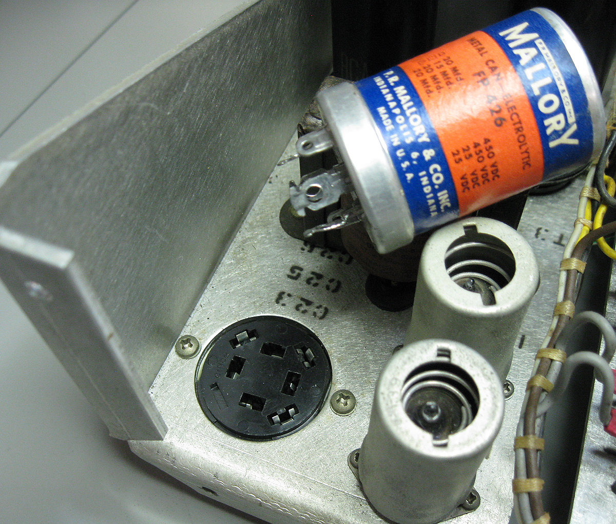
One of the cool little things I discovered in this radio was the use of a socket for the multi-section capacitor. By breaking off a specific twist-lok lug, the capacitor can be "polarized" and only be plugged into this socket in one way. I know some of you have probably seen this before at some point, but is something I have yet to see in Amateur boatanchors of this vintage. It makes it very easy to replace these normally frustrating to replace caps.
The cool thing is I happen to have several brand newly manufactured multi-section caps (CP Manufacturing) of the same cap values but all 450V. Should plug in there no problem.
Here's an image:
- What ... No pots?
Another thing of note in this transmitter is the complete lack of potentiometers. There are none to be found anywhere inside or outside of this transmitter. All resistances are done either via fixed values or adjustable wire wound resistors.
- Full Schematic ... well almost
I did purchase the user manual and schematic for this radio. Unfortunately I quickly discovered the entire center section of the drawing is missing from the scans. The primary circuits are there, but the center of the schematic shows all of the very relevant interconnections between the various circuits. This is what's missing. :(
I will have to contact the fellow I purchased this from and see if he has the originals or whether this is a copy of a copy and this is all he has. If the latter is the case I will redo the schematic myself. I intend to publish this (or the full original) in this article at that time.
The user manual is very good. It has the usual circuit descriptions and such, but the nice thing is the graphs showing the approximate settings for various frequencies for all of the controls. These are displayed as curves on various graphs, and not just simply as a chart or list of numbers as is usually the case.
As I said at the end of Part II, next time we will talk more about the Gates power supply/modulator. Later I will add more details which will include some simple modifications for improved audio, refurbishing the transformer housings (including duplicating the original Triad decals), and other specifics of this restoration.
Many of you may be interested by the decal duplication. This will detail a method where you can perfectly duplicate the "water slide" decals, using your computer, a scanner (or digital camera) and a color printer. This is one my little tricks I do in my restorations for clients. Some of you may be familiar with this method already but for those who do not, it should prove interesting at least. While it's not anything earth shattering, it may prove useful to some who really want to go that extra step to restore the look of a vintage radio.
Stay tuned ...
73'
John LeVasseur, W2WDX
All text and images contained herein are under strict copyright.
Reprinting or publication in any medium is not allowed without express written consent of the author.
Copyright 2012 John LeVasseur