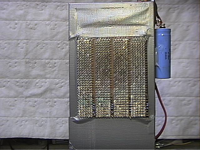
 Array
1 is a frontal view of the 816 LEDS.
Array
1 is a frontal view of the 816 LEDS.This is a new array of LEDS. The base for the array is a 6" x 8" perfboard
purchased at Radio Shack.
There are 34 rows of LEDS in this array of 24 diodes each. Each row of 24 diodes is
broken down further into a six diode segment and a series resistor. The series resistor is
employed to assure equal current into each six diode segment. Then the segments are
paralleled into two 408 LED groups.
Each 408 LED group has its own PowerMosfet that switches the current for the group. The
gate signal for the 2 PowerMosfets originates from the same drive circuit.
Array
1 is a frontal view of the 816 LEDS.
 Array
2 shows a portion of the six diode segments.
Array
2 shows a portion of the six diode segments.
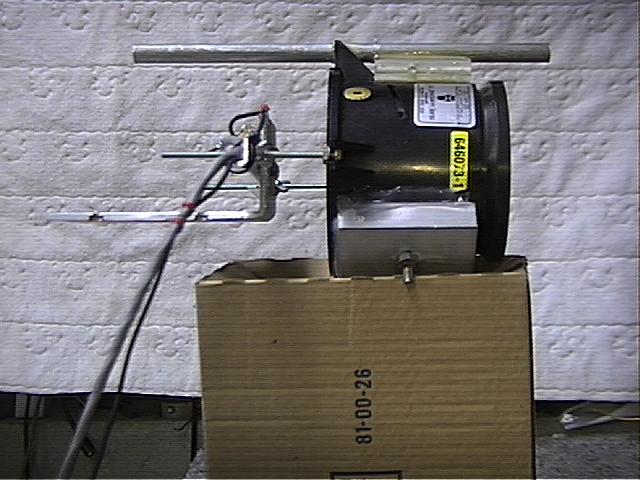
 Array3
and
Array3
and  Array4 show the filter capacitor 22,000 UF at 30VDC, and the
cooling fans that keep the operating temperature within safe operating limits for the
array.
Array4 show the filter capacitor 22,000 UF at 30VDC, and the
cooling fans that keep the operating temperature within safe operating limits for the
array.
The aluminum chassis provides a convenient way of mounting the perfboard LED array and
a plenum for cooling. Duct tape is used to seal the box and to channel all of the air flow
through the small holes in the perfboard, thus cooling the diodes. Not pretty….but
effective.
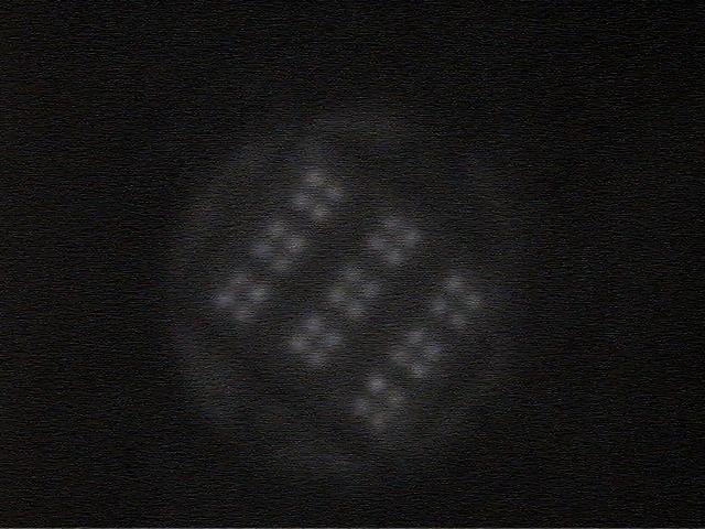
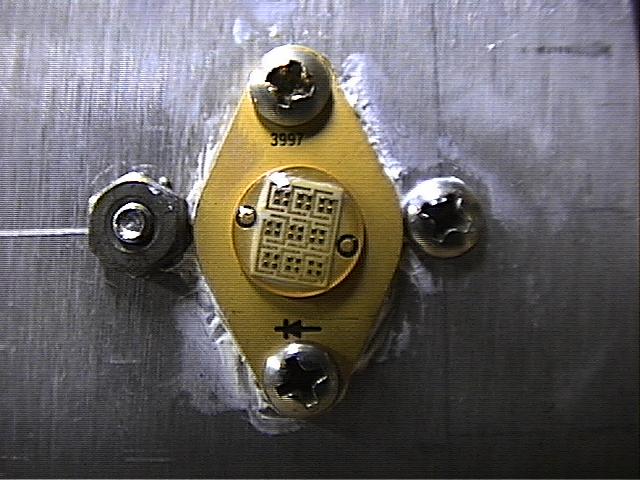
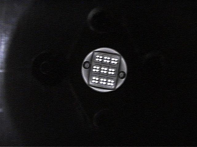
This transmitter was used to make the audio clips.(Techinfo Page) It consists of a 36 diode configuration. The diodes are all mounted in a single TO66 package. The TO66 is mounted about 3 inches behind a television projection lens. This arrangement results in a beamwidth of approximately 10 degrees. This transmitter runs approximately 15 watts of input power.
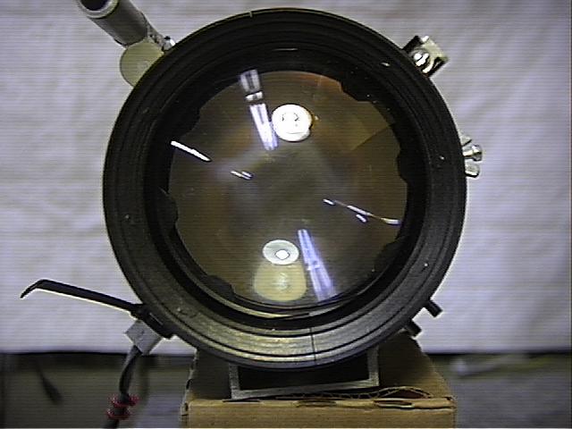
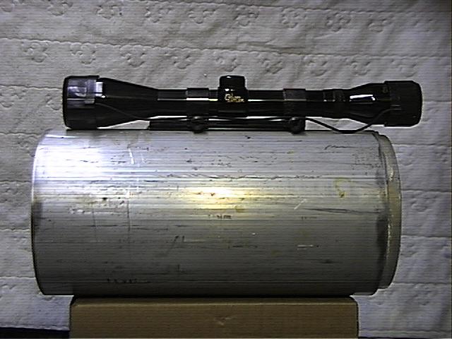
The antenna in an optical receiver system can be either, concave mirror or convex lens. I chose lens, it was easier to mount and I happened to have a 5" lens available.
Several pictures of the original receiver assembly have been included here. A 5" lens is fitted into the end piece of an aluminum pipe. The pipe is lined with black felt. The black felt is used to minimize internal reflections of light entering the tube off axis and mixing with the desired signal at the focal point of the lens. Flocking paper sold by Edmund Scientific would have been a better choice but I had the felt on hand.
Insert the optical detector in the small hole located at the rear of the tube to locate the optimum focal point for different applications. Slide the optical electronics in or out to maximize signal strength. All of the optical detectors are built into aluminum tubing that fit snugly into this opening. The aluminum tubing works great as a 60HZ main shield.


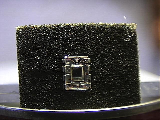
Optical detectors are just small solar panels, with an amplifier after it.
Factors effecting the performance of an optical receiver are:
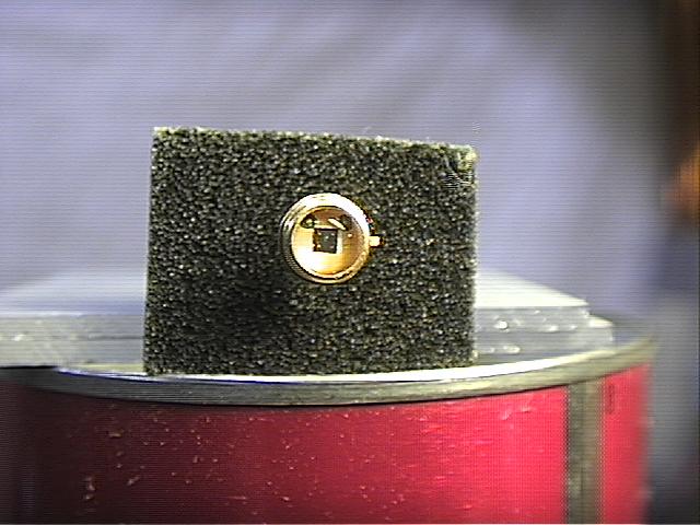
In an optical detector light energy is converted to electrical energy. An extremely small amount of light is focused onto the detector in a cloud bounce application. A very low noise, high input impedance amplifier will need to follow it. The smaller the detector area, the lower the internal noise. Smaller detectors usually have higher frequency response. The detector used for my cloud bounce experiments is a unit from Digikey PDB - 715 - 100 ND, manufactured by Photonic Detectors, Inc.


![]()
![]()