(Click on any picture if you want to see an even larger version of it.)
| Band | QSO's | QSO Points | Grids |
| 50 | 9 | 9 | 3 |
| 144 | 20 | 20 | 6 |
| 222 | 2 | 4 | 2 |
| 432 | 16 | 32 | 5 |
| 902 | 1 | 3 | 1 |
| 1296 | 1 | 3 | 1 |
| Totals | 49 | 71 | 18 worked 5 activated |
| Claimed score = 1,633 points | |||
Pictures of my rover setup for that first contest can be found here.
My second rover experience was in the August 2000 UHF Contest. For this event, I had equipment for 222, 432, and 1296 MHz. Although the event was a much longer contest than the 4-hour Spring Sprint, I had other committments that prevented me from reaching my first grid until 1 hour and 15 minutes before the end of the contest, not counting a single 446 MHz FM contact that I managed to make while driving through EN34 on the way to EN33. I managed 25 QSO's in 10 grids, plus 3 grids activated, for a total score of 1,209. In this contest, the antennas were mounted to a mast in a rotator bolted to the roof rack on my van, so I could park and point the antennas from the rear seat of the van, where the radios were located. Unfortunately, the whole antenna support assembly collapsed shortly after the end of the contest, and I had to dismantle it in a farm field so I could drive home.
Pictures of my rover setup for that second contest can be found here.
Here is what I assembled for the new WØJT rover station:
| Band | Power | Antenna Type | Antenna Gain |
| 50 MHz | 100 watts | M Squared 18.0' boom 6M5X yagi | 9.4 dBd |
| 144 MHz | 160 watts | M Squared 19.5' boom 2M12 yagi | 12.8 dBd |
| 222 MHz | 100 watts | Rear 13' of an M Squared 23.3' boom 222-5WL yagi | < 15.2 dBd |
| 432 MHz | 100 watts | Rear 13' of an M Squared 21' boom 432-9WL yagi | < 17.3 dBd |
| 902 MHz | 10 watts | Directive Systems 12' boom 3333LYK loop yagi | 16.1 dBd |
| 1296 MHz | 36 watts | Directive Systems 12' boom 2345LYK loop yagi | 17.6 dBd |
| 2304 MHz | 15 watts | Directive Systems 12' boom 1376LYK loop yagi | 21.0 dBd |
I have no information on what the gain of the two shortened antennas would be, so I just show it to be something less than the full gain of the unshortened antenna. I would hope that since I retained more than half of the original antenna for the rove, that real gain would be no worse than -3 dB relative to the gain of the whole antenna. Subjectively, however, I can say that the two shortened antennas seemed to perform quite nicely, especially the 432 beam which got a lot more use than the 222 beam this time around.
The constuction technique was as follows, starting from the bottom and working up.
Lined up side-by-side, were a 2x6, a 2x12 and a 2x6. The two outside 2x6's were drilled so that U-bolts could pass through them and grab onto the roof rack. (The 2x12 was also drilled the same way, but I failed to obtain enough U-bolts, so the assembly was held in place by four U-bolts instead of six.)
The 2x6's and 2x12 were covered with a 24" by 48" sheet of plywood, centered on them and running with its length parallel to the support boards. A 24" by 12" sheet of steel was attached to the top and the bottom of this assembly. Four holes were drilled through from the top layer of steel, through the plywood, through the 2x12, and through the second layer of steel. The rotator bolts passed through these four holes, with 3 steel washers under the head of each bolt for strength and proper thread spacing. (I had already destroyed a different rotor once by using bolts that were too long, but that's a story for a different occasion.)

Here is a view of the lumber attached to the roof rack of my van, serving as a base for the rest of the antenna structure. The top steel sheet is already starting to rust. When I dismantle everything, I will sand down the steel sheets and paint them with a rust-inhibiting paint, and will seal the wooden parts with the same product I use to seal and protect my rough cedar house siding.
Into the rotator (Yaesu G-450) is inserted a thick-walled aluminum pipe, 2" OD, obtained from Garelick Steel in Minneapolis. From the very top of this pipe to the ground is approximately 12 feet!
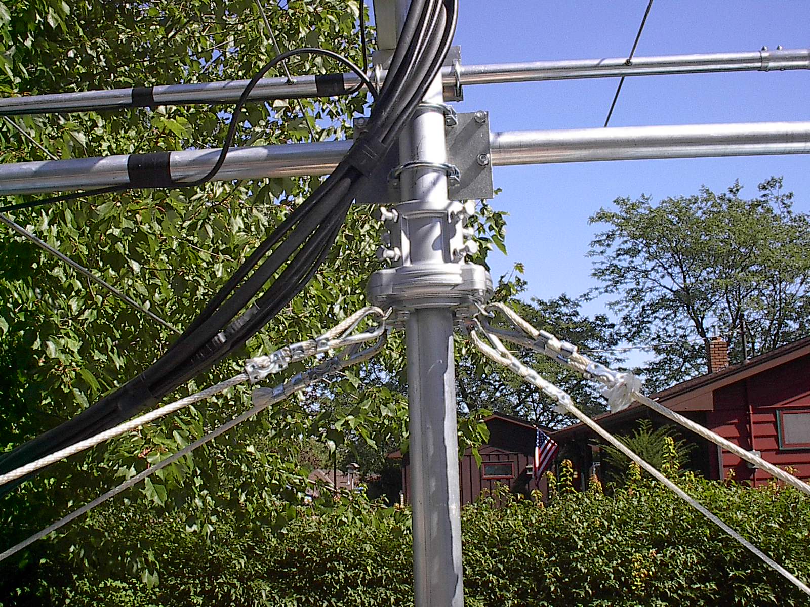
There is a Yaesu thrust bearing above the rotator, with four ropes going to four nylon strap tie-downs hooked to convenient holes in the undersides of the front and rear bumpers of the vehicle.
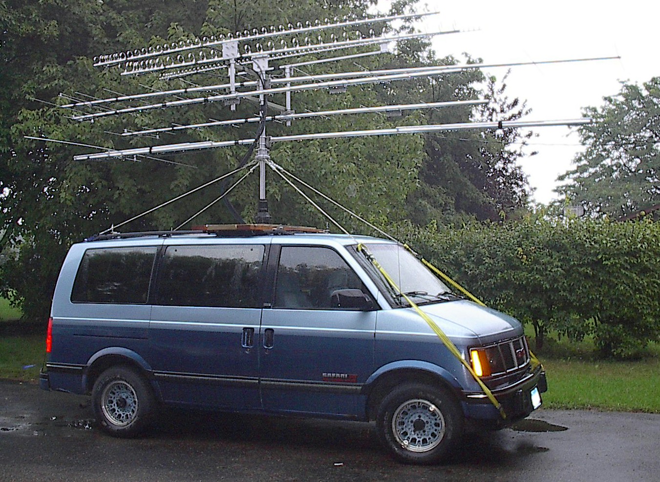
Above the thrust bearing is an M-Squared 6M5X beam for 50 MHz. In the early photos, all the directors and reflectors are folded inwards and wrapped to the boom with velcro straps. Only the driven elements are at their full width, since they cannot be easily shortened. I planned to drive with the antenna elements in this folded position, and with the antenna rotated so that the driven element was vertical (actually, diagonal), so as to not exceed the width of the vehicle. But this would put the tip of the DE higher than the already high antenna stack, risking close encounters with low objects. I decided to leave the antenna in the horizontal position even on the road. This is an absolutely huge 6 Meter antenna for roving, but I used it because I had it, and I wanted a good signal on 6 Meters.
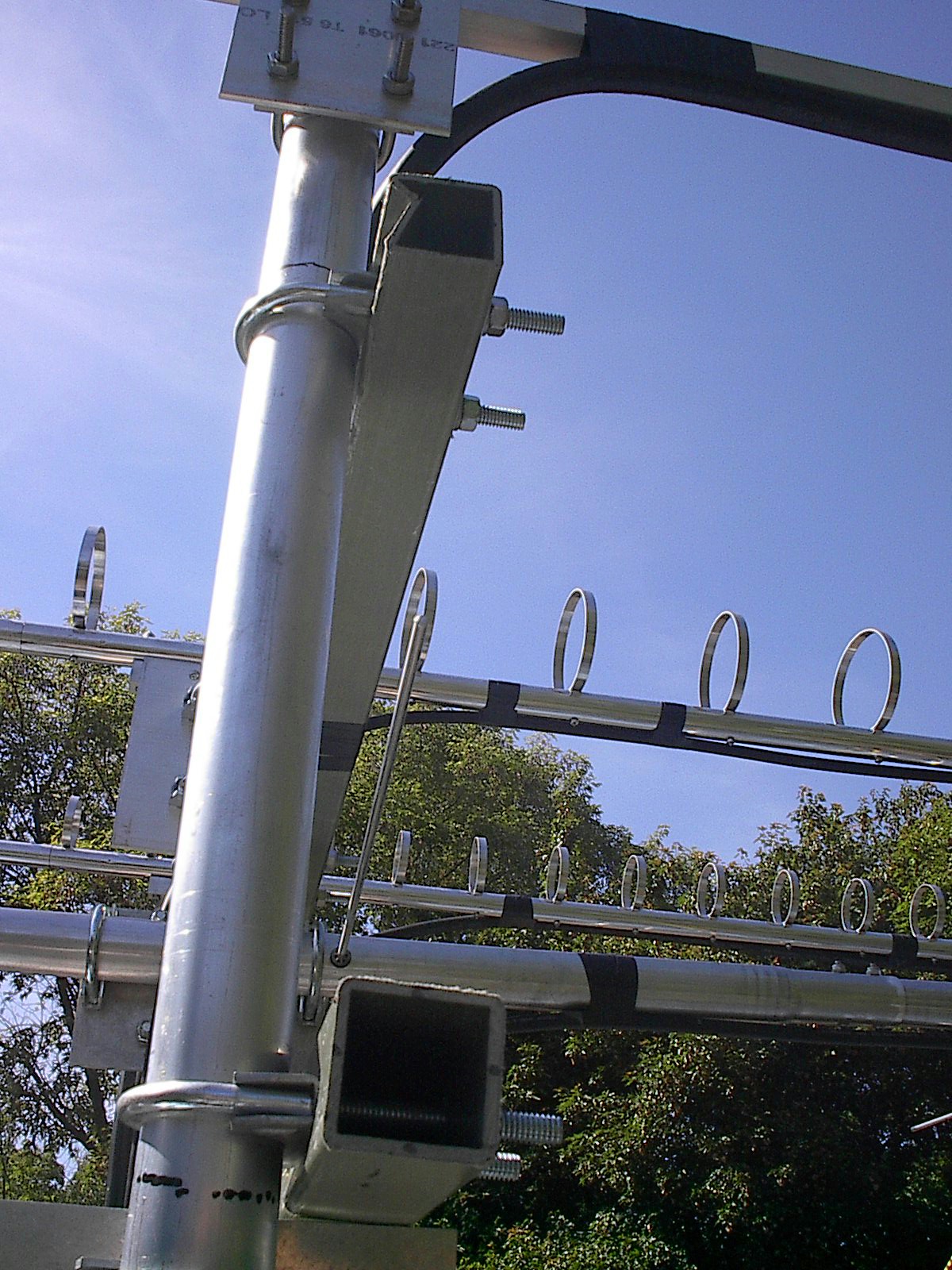
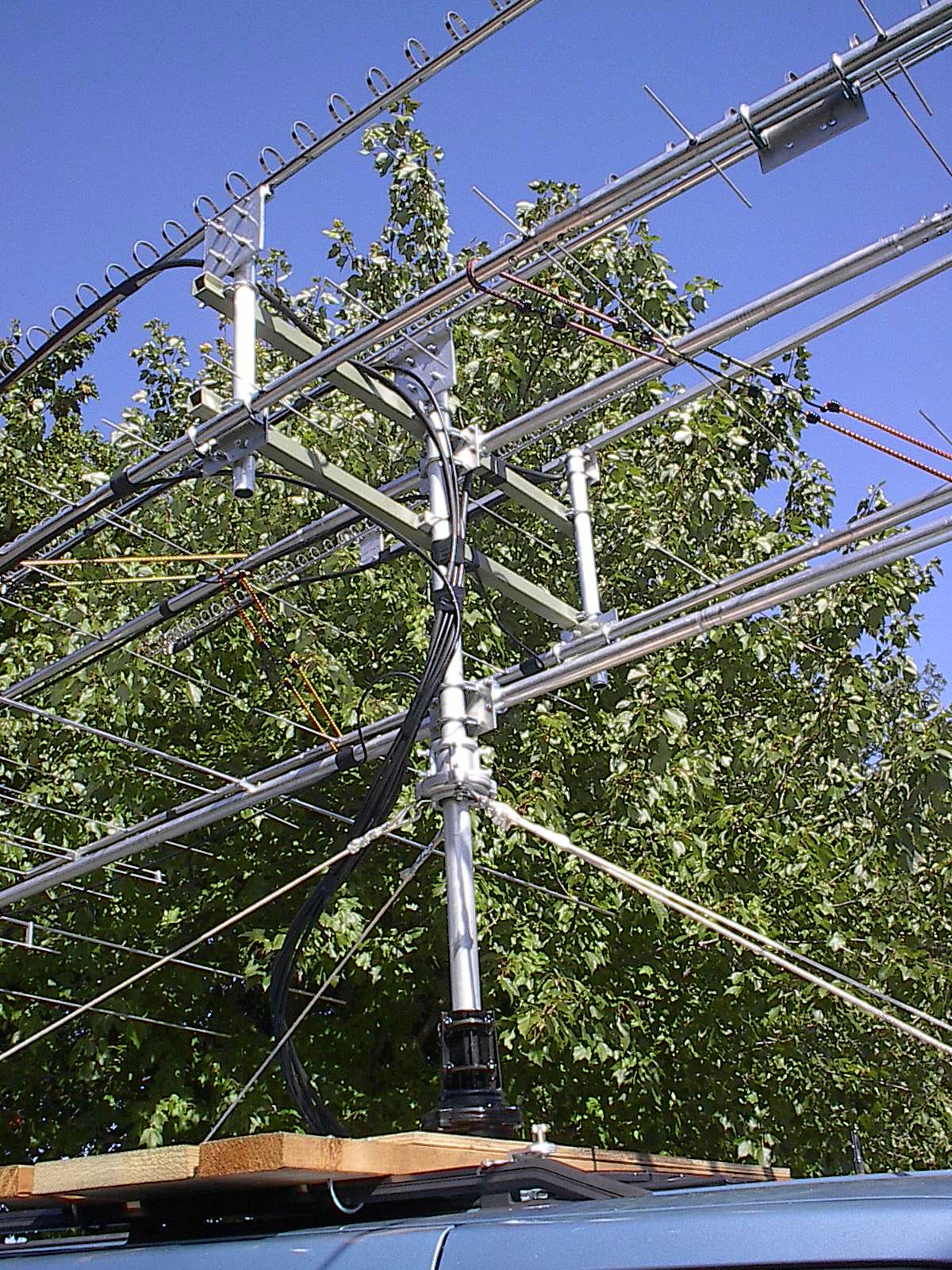
Above the 6 meter beam is a frame composed of two square fiberglass tubes (the olive green horizontal pieces) which are four feet long, and two pieces of thick walled Schedule 40 aluminum pipe, about 1.5" OD, which are two feet tall. (They started out at 3 feet, but I trimmed them to 2 feet when it became apparent that I was running out of vertical space.) Each fiberglass tube is drilled for three pipe clamps, 2" size in the center and 1.5" size on the ends. The horizontal cross tubes are spaced about a foot apart, leaving 6 inches of exposed pipe at the top and bottom of the frame assembly, a total of 4 attachment points. On these four corners are mounted (bottom) 222 and 432 antennas, and (top) 1296 and 2304 antennas. The 902 loop yagi mounts to the 6 inches of center mast that extends up through the middle of the two cross booms, and the 144 MHz antenna is mounted directly below 902, inside the square frame.
Obviously, the antennas are very crowded. Actually, this arrangement would probably be excellent if not for the 50 MHz and 144 MHz antennas, since that would keep the three microwave antennas almost 2 feet apart in the horizontal direction, and nearly two feet above the 222 and 432 antennas, which in turn would be nearly 4 feet apart in the horizontal direction. I had toyed with the possibility of a two-part telescoping mast that I could push up after reaching an operating site, but I finally opted to keep it a bit simpler since I would not have any partner with me to help with setup and teardown. And as it turned out, the antenna assembly wasn't finished until Friday night before the Saturday start of the contest, so any more complexities in the design and I might not have finished before the contest start.
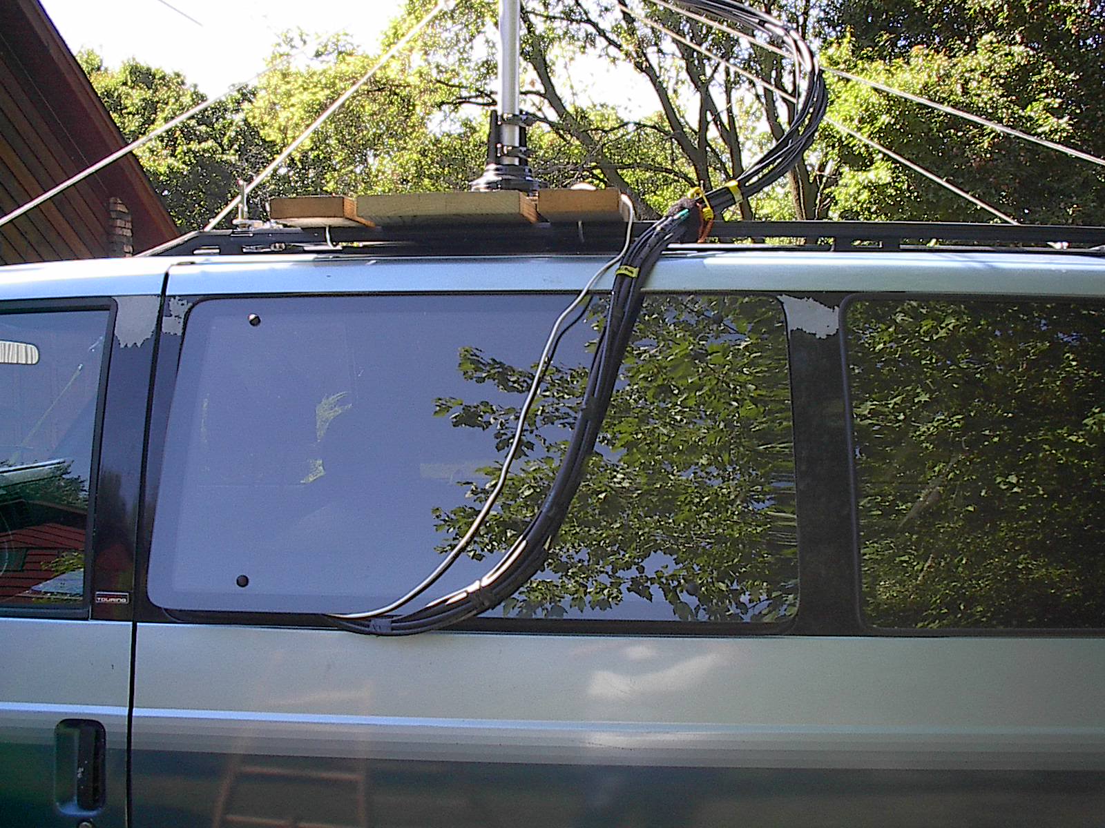
Feedlines were composed of what coax I already had lying around that had connectors already attached. I vowed I would not be attaching N connectors to coax in the wee hours of Saturday morning like I have done for some contests, and this was one of the few promises to myself that I actually managed to keep. For 2304 MHz and 1296 MHz, I used LMR-600UF. (Oddly enough, the LMR-600 is the same diameter as the boom of the 2304 loop yagi!). For 902, 432, and 222 MHz, I used LMR-400UF. For 144 and 50 MHz, I used some (Ugh!) RG-8 with PL-259's. All feedlines were taped together into a large bundle, a loop was left for strain relief during rotator operation, and the bundle fed in through the bottom of a pop-out window on the driver's side of the vehicle, as shown. The microwave feedlines needed short jumpers of LMR-200 or RG-142 to the SMA outputs of my T/R relays, inside the vehicle.
Here is the view of the operator's station inside the van. The van is a 1992 GMC Safari van with all-wheel drive and two removable bench seats in the rear compartment. I kept the rearmost bench seat in place and removed the center bench seat. A folding table took its place.

At the far left is the laptop I used for logging. This is a very old Pentium 90 machine with 32 Mb of RAM and a 640 Mb hard drive. This would have been more than adequate, except for two serious shortcomings that gave me grief during the contest: the video display is only 640x480 pixels, not quite big enough for some of the functions of the VHF-DX logging software I was using, and the battery has nearly zero charge capacity left in it. I had to run it from the AC inverter through its battery charger (no DC charger available to me), and when the AC failed (more on that later), the laptop would go dead within a minute or less.
The laptop I was planning to use was a much nicer one with none of these shortcomings, however it developed an overheating problem due to a failure in its internal cooling fan circuitry. It was sent in to the manufacturer for repairs, and came back a couple of weeks before the contest, but the fan failed again! In hindsight, I would have probably been better off with keeping a paper log, but remember, I was expecting to make LOTS of contacts with this setup, so I went ahead and used this borrowed, sub-optimal laptop.
Behind the laptop are three "bricks" for 432, 222, and 144 MHz. (You can't see the 432 brick with the laptop screen in the upright position.) On top of the bricks I have power/SWR meters for 222 and 144 because I have to watch the drive levels into those two bricks carefully. Their designed drive levels (2 watts and 10 watts, respectively) are much lower than what the corresponding transverter or radio can provide.
The next stack to the right of the bricks has the Icom IC-251 radio on the bottom (144 MHz IF rig for the microwave transverters), with the Yaesu FT-847 radio on top of it (for 50, 144, and 432 MHz). Above them are the 222 transverter interface boxes, one provided by Downeast Microwave and an auxiliary box I designed and built myself. Above them is the controller for the Yaesu G-450 rotator.
To the right of those units is the Icom 706 MkII used as the IF rig for the 222 transverter, and planned to eventually be the IF rig for all the microwave bands. (More projects for which the proverbial Round Tuit has never materialzed.) There is an MFJ CW keyer above it. The IC-251 has no built-in keyer, it only works with a straight key (or an external keyer).
At the far right edge of the card table are the 120 VAC inverter (in the blue box) and the Bencher CW paddles temporarily sitting on top of it. Bungee cords and nylon strap tie-downs hold it all in place even while in motion on the road.
Not visible (because they are under the table) are the microwave transverters and associated IF switching and T/R relay switching boxes.
Saturday morning arrived, and the final allotment of gear and supplies were packed into the van (in the rain, no less). It was time to hit the road. Unfortunately, rule number one has already been broken badly. (Test everything before you leave home.) None of the radio gear had actually been tested in this rover setup, but in my defense, most of it was in active use in my home station, and I have torn down my shack and re-assembled it for Field Day or for portable contest operations often enough that I was not worried about getting that part right. What I was worried about was driving down the road with this 12-foot-plus high stack of aluminum perched on my roof, since the vehicle hadn't been moved out of my own driveway until this point. So, with much trepidation, and with the windows rolled down so I could hear any ugly sounds that might signal impending mechanical failure, I eased out onto the street and headed for the expressways (via a route that does not suffer from the low-hanging tree limbs of my usual route).
My destination was the four grid corners near Elbow Lake, MN. I planned to activate EN15, EN25, EN26, and EN16 from there. The map below gives you a rough idea where I was headed. It is basically very close to the place where North Dakota, South Dakota, and Minnesota all border on one another.

I left home (Apple Valley, MN) a couple of hours later than expected, but in good spirits. After a few "close encounters of the idiot driver kind" on Highway 77 and Interstate 494, I finally reached the "open road" of Interstate 94 West. Although I could detect no obvious problems with the antenna assembly while driving, I decided to be my usual cautious self, when I saw a sign for an upcoming rest area. I pulled off the Interstate to inspect the antenna array to see how it was faring in the wind.

Here you see my vehicle in the truck parking area of the rest stop, with my handy aluminum folding ladder in one of its myriad possible unfolded configurations. Don't worry, it's only an optical illusion -- the antennas are not taller than the tractor-trailer parked alongside me! But what I found was somewhat disconcerting. I discovered the weakest link in my antenna array, the fiberglass cross-booms. Both of them had cracked and become more rectangular than square in cross-section at the points where the vertical aluminum tubes attached. This had loosened their hold on the vertical tubes, and allowed the antennas to start swinging outwards in the 55 - 65 MPH "breeze" of Interstate Highway travel. At this stop, I simply re-aligned the errant antennas and tightened up the U-bolts as much as I dared. As it turned out, this would not be not good enough.
I made another stop along the way, when it seemed that the wind resistance had gone up considerably. The antennas on the support structure had started swinging sideways again, and I realized that further tightening of the U-bolts would accomplish no good. It would simply deform the fiberglass tube even more. I resorted to liberal application of bungee cords running between the 222 and 432 antennas to the centrally-located 144 antenna. One set was placed ahead of the central mast, and one set was placed behind the central mast, to try to prevent the antennas on the short vertical aluminum tubes from twisting either right or left again.
If you look carefully at the bottom cross boom in the picture above, you can see it is basically square in cross-section, but it is bowed inwards slightly where the U-bolt clamps it to the vertical mast section. But look at the top cross-boom. It is no longer even remotely square! The left edge of it as you view the picture is "folded" inwards, making the cross-section pentagonal instead of square!
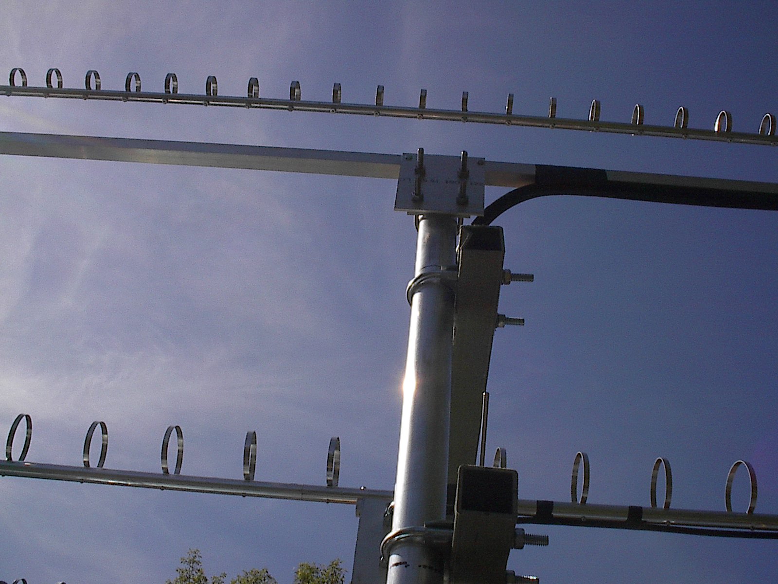
In the photo above, you can get a better idea of the design of the cross-boom assembly, and you can now see the bungee cords that were applied to keep the antennas from twisting left to right due to the damaged fiberglass tubes. (Sorry about the extremely "busy" background of foliage behind the antenna array.)
I had my sites all picked out for the Saturday session out Northwest of the Twin Cities metro area. Unfortunately, having broken rover rule number 2 (Visit your operating sites in advance, or ask an experienced rover who's been where you're going, don't just rely on maps), I found that my planned EN15 and EN25 locations would not work. What I thought (from various maps and even satellite photos on the web) was a minor road into a public park turned out to be a private driveway! I might have considered asking the farmer if I could work from there anyway, except that the sites were really no good -- I would have been surrounded by a house, two farm sheds, and a large metal building. (The two red dots on the map below were the sites I had to abandon.) Time to find replacement locations!
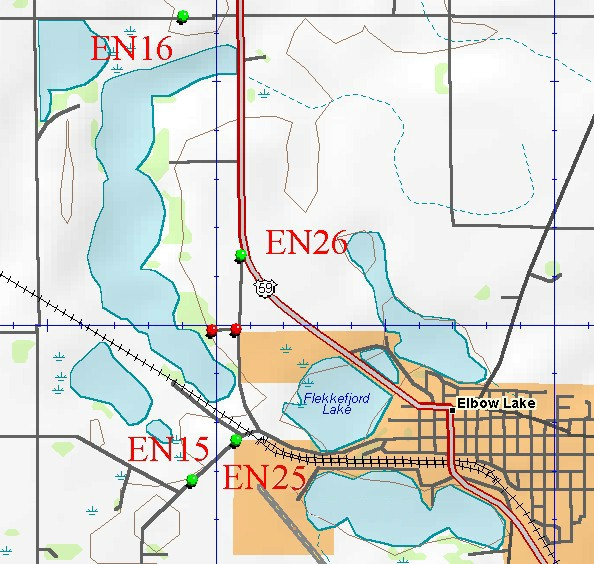
Fortunately, the area in question is remote enough that I quickly found another pair of spots where I could go from EN15 to EN25 with only the bare minimum 100-meter drive required by the rules. The map above shows the locations I finally used in the four grid corners as green dots. So I parked, unfolded the directors and reflectors on the 50 MHz beam, turned on all the gear, booted up the laptop, and started calling "CQ Contest" with my antennas pointed at the Twin Cities.
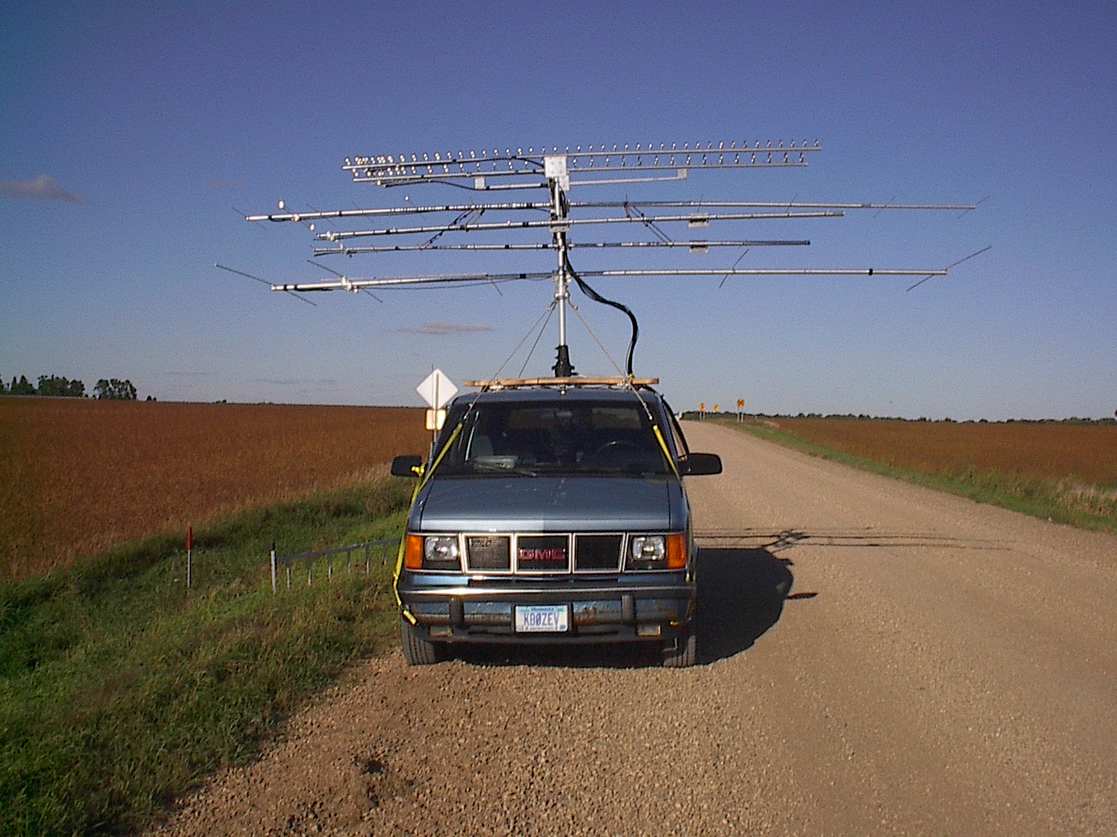
If you look very carefully, you can see the bungee cords that kept the antennas on the vertical supports from continuing to twist left and right in the wind. And if you look really, really carefully, you will notice that I failed to unfold one of the directors on the 6 meter beam. I didn't notice that until Sunday morning!
My van is parked facing basically Southwest, and the antennas are pointing to the right of the picture, or to the driver's side of the vehicle, basically to the Southeast (towards the Minneapolis-St. Paul Twin Cities metro area).
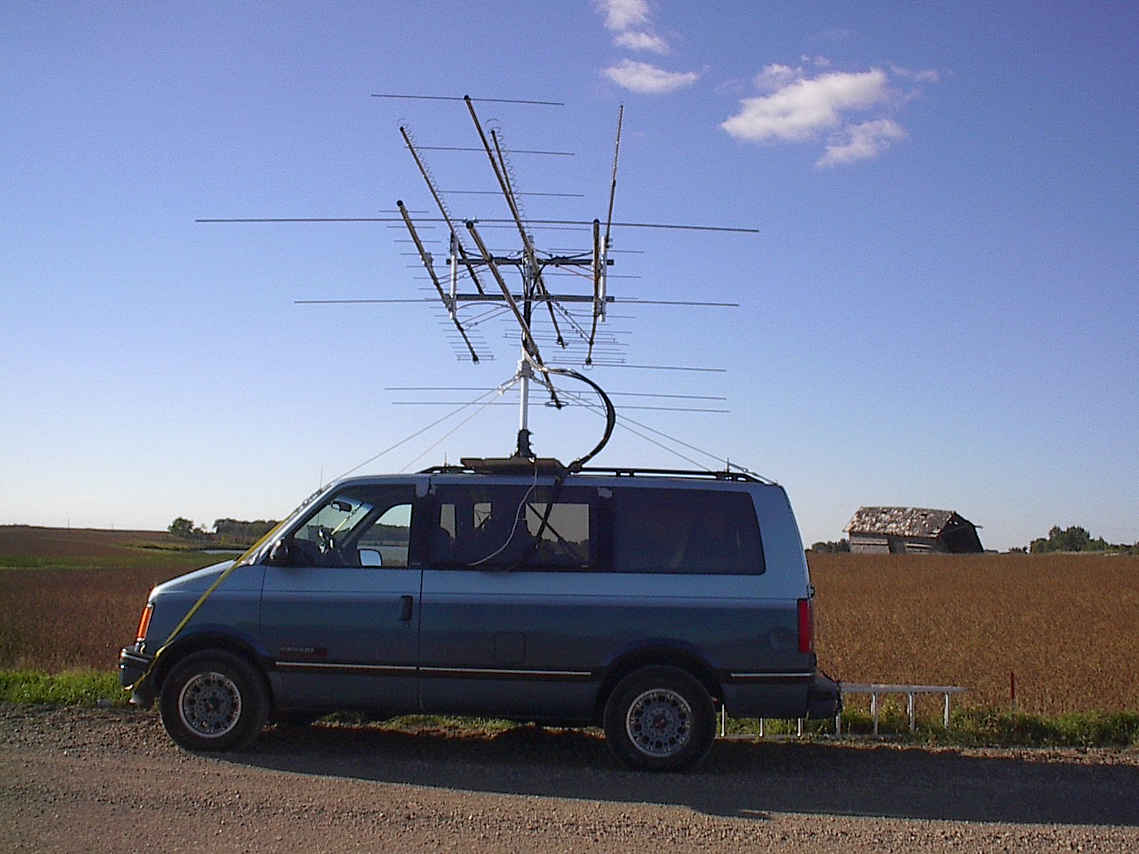
Here's another view of my setup in EN15. The angle of the shot is a bit misleading. The antennas are not angled upwards like it seems. It is now easier to see the four sets of bungee cords being used to (try to) keep all the antennas pointing in the same direction. You may notice that the 2304 beam (top right loop yagi with the tiniest loops) is not quite pointing in line with the rest, although some of that offpointing is another optical illusion of the photo angle. However, there is another small problem there that needs to be addressed before I do this again. While I like the Directive Systems loop yagis quite a bit, I am dissatisfied with the design of the boom-to-mast plate mounting system, which is too flimsy for my taste.
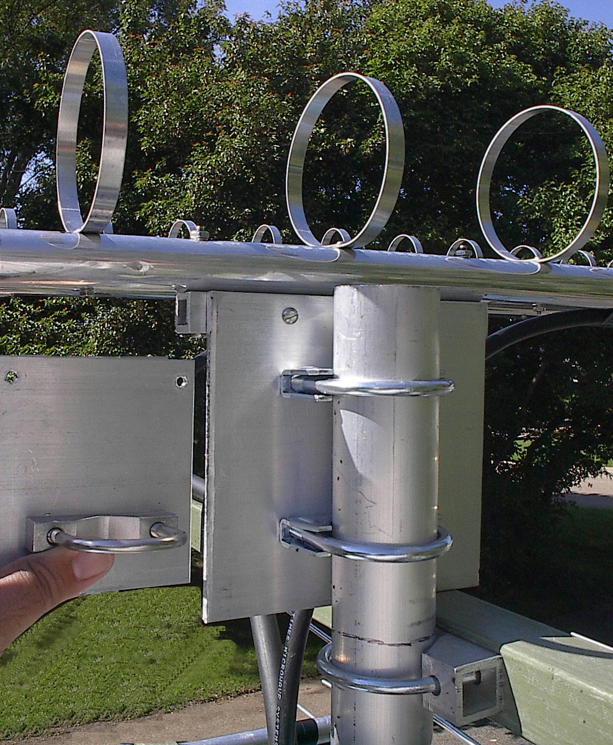
I had replaced the mounting plates for the 902 and 1296 antennas with plates of my own design, as shown in the photo above. (The original plate is to the left, being held in my left hand, and the new plate is shown in place on the mast.) The replacement plates are much stronger, and capable of mounting with either 1.5" or 2" U-bolts. The aluminum plate is 6" square, and much thicker than the original plate. It allows for the use of two 2" U-bolts spaced fairly far apart, for maximum stability, rather than a single 1.5" U-bolt which allows the antenna to rock up and down. This was an absolute necessity for my 902 MHz beam, since it was mounted to the center mast which was 2" in diameter, too large for the stock plate.
But, since I was running out of time during the antenna assembly phase (those three microwave antennas had over 150 loops to be attached to the booms!), I elected to just modify the 2304 loop yagi mounting plate by drilling two more holes and adding a second 1.5" U-bolt to it, instead of completely replacing it. Even with the second U-bolt in place, it allows too much antenna movement on the mast at 70 MPH. (The antenna can tip upwards and downwards in a stiff wind.) Another task waiting for me to get a Round Tuit.
So anyway, as I said, I pointed to the Twin Cities and started calling. And I was greeted with a lot of silence. As it would turn out, I worked absolutely no one that I expected to work, either in the Twin Cities, or in Sioux Center Iowa, from any of the four grids in this corner of the state. I did hear Gary (WØGHZ) once, talking to someone closer to him, and the last thing I heard him say was "turning the antennas to the West". I called him immediately, but I was too late. He was already pointed too far to the West to hear me. I did hear Mike (KMØT) once, but could not get his attention at the time, either. I never heard either of them again.
I did manage to work one other station in EN13, and two stations in EN44, from these locations, distances of up to 233 miles, so it seems that my gear should have been good enough for me to reach the folks I expected to connect with in MN and IA. But I guess no one was pointed in my direction at the times I called (and called and called).
I soon found that I had been mistaken when I assumed I was making this rove alone. It turns out that Murphy had come along on the ride with me!
At one point, I heard a station in Wahpeton, North Dakota, that I wanted to work. Of course, from where I was located, that was no great feat, since I was practically in his back yard (well, really about 30-40 miles away). But he was in a different direction than where I was pointed. So I swung the beam towards where I thought he was located, and called for him on 144.200 MHz. I asked him for some chatter so I could peak up on him. I unkeyed, listened, reached for the antenna rotator control, and tried to optimize my pointing angle, but nothing happened. Huh? Then all of a sudden, my laptop started beeping at me, and a warning box popped up onto the screen, alerting me to nearly dead batteries and imploring me to either shut down or plug in to an AC supply. Wait a minute, I am plugged in! Then I noticed that the IC-251 radio had gone dark. (It runs off of AC, because I can't find the proper DC power plug to bypass the built-in AC power supply.) Conclusion: my inverter isn't inverting! That's really odd, because its power light was still glowing green, the red undervoltage light was not lit, and its internal cooling fan was running. I turned off the inverter, turned it back on, and the IC-251 sprang back to life, as did the rotator. An isolated fluke? Not really. At certain antenna angles, any time I keyed the 2 meter transmitter, the inverter stopped working. None of the other bands seemed to induce this problem, only 2 meters. Arrggghhh!
Now wait a minute, I used this same inverter and rotator once before and had no such problems. What gives? Finally, it dawned on me that the prior outing where the inverter and rotator were used was a UHF contest, where my lowest transmitted frequency was in the 222 MHz band! Although all the gear had been tested at one time or another, and much of it in a situation similar to the current one, not everything had been tested together. And, of course, Murphy enforced his Law.
To make a long story somewhat shorter, I finally resorted to moving the inverter onto the operating table where I could easily reach over to turn it off and on again each time it went dead. Because it "only" was a problem on 2 meters, and (initially) it occurred only when I was pointed in particular directions with the rotator, I managed to continue to work the four grid corners, but with difficulty. Unfortunately, my plan had been to call extensively on 144.200 MHz to scare up some contacts, and then move them through the other half-dozen bands (well away from the calling frequencies) to run up the score. This became a real challenge when transmitting on 2M killed the inverter and rotator.
So I finished the 4 grid corners much later than expected, with very few QSO's or grids in the log. I decided to pack it in for the night. The plans had called for me to drive most of the way home, stopping in Monticello, MN, to activate EN35. Dead tired, hours behind schedule, ego seriously deflated, and facing a planned stop in pitch darkness at another location I've never actually visited, I decided to skip EN35 and just go home and go to bed.
The rest of my operating plan, after getting a good night's sleep in my own bed, was to go through my usual Sunday morning routine, including 11:00 AM church services, then head home, change clothes, load a few supplies into the van, and head to the Southeast towards the grid corners of EN33, EN34, EN43, and EN44, a short distance to the East of St. Charles, MN. Unfortunately, my wife had some other plans for the immediate post-church-services time period, so I got a late start on the second day also. (Second violation of Rover Rule #3, Be at the location you said you'd be at, when you said you'd be there!. Well, at least it takes three strikes before you're called out.
Based on my poor luck with contacting any of the locals on Saturday night from far away, I decided to modify my plan slightly. I got onto County Road 42, that would have taken me to US Highway 52 and on past Rochester, MN to St. Charles, but I pulled off the road just East of Rosemount, MN, only a few miles away from my home in Apple Valley. I decided to make my presence known to the locals from right nearby, there in EN34, and rack up some QSO points and multipliers, activate the bands that had gone unused to this point, and make the locals aware of my revised schedule to the Southeast grid corners.
This turned out to be a fortunate change of plans, because I did manage to finally activate the 222, 902, and 1296 MHz bands from this spot, and did accumulate a small but significant number of QSO's on the "meat and potatoes" bands (50, 144, and 432 MHz). But the problems mushroomed out of control. The 902 and 1296 contacts were barely accomplished, over about a 13-mile path, and these transverters have worked over a 190-plus mile path in the past, so something was seriously not right. Perhaps I was not pointed at Lenny (KØSHF) accurately enough, but the problems with the AC inverter got worse and worse, until I finally had to give up after less than an hour of actual operating time. I pointed the antennas towards the front of the van, turned off all the radio gear, jumped into the driver's seat, and went home, where I collapsed in disgust.
| Band | Mode | Date UTC | Time UTC | My Grid | His Call | His Grid | Miles |
| 144 | SSB | 2002-09-14 | 22:32 | EN15xx | N0QAC | EN16qg | 35 |
| 432 | SSB | 2002-09-14 | 22:33 | EN15xx | N0QAC | EN16qg | 35 |
| 144 | SSB | 2002-09-14 | 22:45 | EN15xx | N0MSS | EN16qg | 35 |
| 432 | SSB | 2002-09-14 | 22:52 | EN15xx | NOMSS | EN16qg | 35 |
| 50 | SSB | 2002-09-14 | 22:55 | EN15xx | N0MSS | EN16qg | 35 |
| 432 | SSB | 2002-09-14 | 22:59 | EN15xx | WB0HHM | EN13pm | 173 |
| 144 | SSB | 2002-09-14 | 23:03 | EN15xx | WB0HHM | EN13pm | 173 |
| 144 | SSB | 2002-09-14 | 23:29 | EN25ax | N0QAC | EN16qg | 35 |
| 432 | SSB | 2002-09-14 | 23:30 | EN25ax | N0MSS | EN16qg | 35 |
| 432 | SSB | 2002-09-14 | 23:31 | EN25ax | N0QAC | EN16qg | 35 |
| 50 | SSB | 2002-09-14 | 23:33 | EN25ax | N0MSS | EN16qg | 35 |
| 144 | SSB | 2002-09-14 | 23:37 | EN25ax | N0SRQ | EN18vc | 147 |
| 432 | SSB | 2002-09-14 | 23:41 | EN25ax | N0SRQ | EN18vc | 147 |
| 144 | SSB | 2002-09-15 | 00:31 | EN26aa | N0AKC | EN44gt | 233 |
| 144 | SSB | 2002-09-15 | 00:32 | EN26aa | KB9PJL | EN44gt | 221 |
| 144 | SSB | 2002-09-15 | 00:32 | EN26aa | N0MSS | EN16qg | 35 |
| 144 | SSB | 2002-09-15 | 00:34 | EN26aa | N0QAC | EN16qg | 35 |
| 144 | SSB | 2002-09-15 | 00:36 | EN26aa | N0SRQ | EN18vc | 146 |
| 432 | SSB | 2002-09-15 | 00:47 | EN26aa | N0MSS | EN16qg | 35 |
| 50 | SSB | 2002-09-15 | 00:48 | EN26aa | N0MSS | EN16qg | 35 |
| 432 | SSB | 2002-09-15 | 00:49 | EN26aa | N0QAC | EN16qg | 35 |
| 144 | SSB | 2002-09-15 | 01:06 | EN16xa | N0MSS | EN16qg | 34 |
| 432 | SSB | 2002-09-15 | 01:08 | EN16xa | N0MSS | EN16qg | 34 |
| 50 | SSB | 2002-09-15 | 01:08 | EN16xa | N0MSS | EN16qg | 34 |
| 144 | SSB | 2002-09-15 | 01:09 | EN16xa | N0QAC | EN16qg | 34 |
| 432 | SSB | 2002-09-15 | 01:10 | EN16xa | N0QAC | EN16qg | 34 |
| 144 | SSB | 2002-09-15 | 21:04 | EN34kr | KT8O | EN34iv | 15 |
| 144 | SSB | 2002-09-15 | 21:05 | EN34kr | K0CJ | EN34is | 8 |
| 144 | SSB | 2002-09-15 | 21:05 | EN34kr | W0EPZ | EN35jb | 22 |
| 144 | SSB | 2002-09-15 | 21:05 | EN34kr | N0KP | EN34gt | 19 |
| 144 | SSB | 2002-09-15 | 21:06 | EN34kr | KC0FXY | EN34fu | 22 |
| 144 | SSB | 2002-09-15 | 21:13 | EN34kr | K0SHF | EN34jv | 13 |
| 50 | SSB | 2002-09-15 | 21:14 | EN34kr | K0CJ | EN34is | 8 |
| 50 | SSB | 2002-09-15 | 21:14 | EN34kr | KT8O | EN34iv | 15 |
| 50 | SSB | 2002-09-15 | 21:14 | EN34kr | N0KP | EN34gt | 19 |
| 50 | SSB | 2002-09-15 | 21:14 | EN34kr | K0SHF | EN34jv | 13 |
| 432 | SSB | 2002-09-15 | 21:16 | EN34kr | KT8O | EN34iv | 15 |
| 432 | SSB | 2002-09-15 | 21:16 | EN34kr | K0CJ | EN34is | 8 |
| 432 | SSB | 2002-09-15 | 21:16 | EN34kr | N0KP | EN34gt | 19 |
| 432 | SSB | 2002-09-15 | 21:17 | EN34kr | K0SHF | EN34jv | 13 |
| 144 | SSB | 2002-09-15 | 21:24 | EN34kr | N0RPM | EN35hb | 25 |
| 222 | SSB | 2002-09-15 | 21:27 | EN34kr | K0SHF | EN34jv | 13 |
| 1296 | SSB | 2002-09-15 | 21:30 | EN34kr | K0SHF | EN34jv | 13 |
| 222 | FM | 2002-09-15 | 21:31 | EN34kr | N0RPM | EN35hb | 25 |
| 432 | SSB | 2002-09-15 | 21:35 | EN34kr | N0RPM | EN35hb | 25 |
| 50 | SSB | 2002-09-15 | 21:39 | EN34kr | N0RPM | EN35hb | 25 |
| 902 | SSB | 2002-09-15 | 21:44 | EN34kr | K0SHF | EN34jv | 13 |
| 144 | SSB | 2002-09-15 | 21:48 | EN34kr | WB0LJC/R | EN34 | (unk) |
| 432 | SSB | 2002-09-15 | 21:51 | EN34kr | WB0LJC/R | EN34 | (unk) |
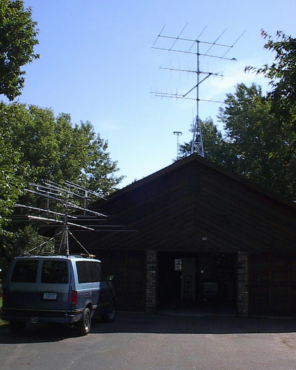
That's hard to say. If you look at the picture below, the odd thing is that the antennas for the four lower bands (50, 144, 222, and 432 MHz) on the roof of the van are bigger than the corresponding antennas on the tower, and there are no tower-mounted antennas for 902, 1296, or 2304 MHz at present. Taking it one step at a time, my immediate plans are to "fix" that discrepancy. The four antennas for the lower bands need to go up onto that tower (and there are twin siblings for the 144 and 432 antennas still in the boxes, in the garage, with two-port power dividers, waiting to go up when the others do). And there are longer versions of the 902 and 1296 MHz antennas already assembled and waiting in the garage to go up onto the tower. And an identical 2304 MHz antenna for the home station is in the box, awaiting my efforts to attach all 76 loops to its boom. Not to mention, loop yagis for 1269 MHz and 2400 MHz (Oscar 40), and an elevation rotor.
Once that work is done, I will have more conservative (but still very useful) antennas for the four lower bands to use on the rover, plus the three rover loop yagis I used this time, assuming I am brave enough or crazy enough to do it again. And, of course, I've learned even more new lessons, to apply to the next time I go out as a rover station.
(Saga to be continued... Based on past experience, maybe in 2 years or so.)
73 de WØJT/R
September 21, 2002