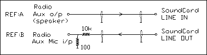
|
Talking about VOX, I received
an email off Mike Waters, W0BTU. It is well worth reading giving the virtues
of VOX over PTT see
http://www.w0btu.com/digital_modes.html
After
believing that Radio Shack does not handle these transformer it turns turns
out that they do.
Radio Shack does have transformers available. Many thanks to
Steve,
KB0OLF for this information. The
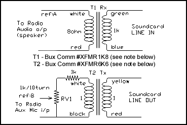
Radio Shack stock number 273-1374 is a 1:1
transformer with an impedance of 600-900 ohms, designated T2 in our
schematics, and the 273-1380 has an input
impedance of 1K ohms and output of 8ohms, T1 in the schematics.
Another source is Bux Comm at Warehouse 209; Office
211; Luenburg Drive; Evington, VA 24550; FAX 434 525 7818 or email
Buck at [email protected] and
tell him I sent ya! ... yea! he'll charge you double. :) Take a
look at Buck's web page for these items at
http://www.buxcommco.com/
And while we are on the subject of transformer availability, I
received this great tip off Peter Jackson, G3KNU who reports that, "I
have found that transformers off telephone modem cards work FB, there are
plenty of them at rallies now that lots of folk are going broadband. I
picked some cards up for 20p". Hey! it doesn't get any cheaper
than that folks! Thanks for the tip Peter.
|
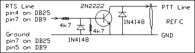
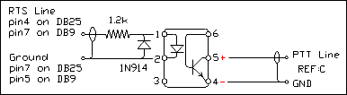
Now, a very simple transistor circuit can be added to automatically switch the PTT circuit on the Rig. This uses the RTS line in the active Comm. Port. The voltage swing on this is -12v/-5v through +12v/+5v so this line is always 'hot'. To isolate the RTS line from other devices being used on the same Comm. Port, you might need to incorporate a switch.
Important: Please check that the PTT line, and/or the Keying line on your rig has a positive voltage on it and it requires a pull-down to ground to activate. These circuits will not work otherwise.
What does that mean? Well, you don't need to use a separate Comm. Port just for this application. I have a Kantronics KAM (all mode TNC) connected to Comm. Port 1 and use the same Port for my sound card modes. The KAM is switched off during sound card mode operation. |
 |
I take off the RTS, DTR and GND lines from the Comm. Port at the RS232 connector going into the back of the KAM. Since the KAM will drag the DTR line down, leave it disconnected at the KAM connector. The KAM does not use it anyway! |
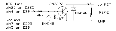 |
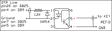
Ok! Included on this web site is a really nice keyboard CW program. I like the idea of being able to simply click an Icon and start operating one of a growing number of Sound Card modes now available. So CwType uses the Comm. Port DTR line to send Morse Code. |
| So! you have realized that with the inclusion of the TTL circuits shown above that you now don't have 100% Radio to Computer isolation. |
Even worse maybe you still have a ground loop problem. Well simply substitute one or both of these schematics for there equivalent TTL version. They are the same as the two TTL circuits above except that they use an Opto Isolator to switch the circuit.
The Opto Isolator is a 4N25, 4N29, ECG 3084, PS2601 or equivalent from Digi-Key,
Newark or Radio Shack, I used a TIL111.
Uhmm! Just received this really helpful email off Kevin, AC0EQ.
"You can get
Opto-Isolator free samples from Fairchild Semiconductors by clicking
HERE."
|
|
An e-mail off Ken, W7LAR gives us a great tip by the way. If you want to get the Optoisolator from Radio Shack it will probably not be a store stocked item. You can get it direct mailed to your home by asking the shop clerk to order it for you from there warehouse. It is number 11305190 and costs about $3.00
Bill Strong also added that he also had problems getting Radio Shack parts but suggested going to a company called Mouser. "They advocate a call for non listed values and odd parts, 800-346-6873 Ordering can be done via Email or Phone. The On Line catalog list all.
www.mouser.com" Thanks for the info Bill. |
Now, for you guys who have
negative keying on those older rigs. This problem is not as straightforward as it first appeared. An email off Bob, W2SR pretty well sums it up.--
Using a classic rig like those made by Drake, Collins and Heathkit present a problem. Just how do you key a transmitter that has -30 to -90 volts on
the keying line? Not with your average 2N2222 or 4N33! So I looked into it
and I will not try and reproduce the schematics here but will point ya! in
the right direction. The first, known as the Jackson Harbor Approach, uses a
high voltage transistor, MJE350. Unfortunately this kit is no longer
available however if you go to
http://jacksonharbor.home.att.net/keyall.htm
you will find that Chuck Olsen, WB9KZY has designed a
replacement called, The Keyall. He tells me it can key grid
block (negative), cathode (high positive) and
regular 13.8V solid state rigs - it can even key the Tuna Tin 2 transmitter
- it's a solid state relay circuit. Thanks Chuck for this excellent kit.
Also checkout Radio Adventures who have a Grid-Block Adapter that is good to -200v see
http://www.radioadv.com/ham_radio_equipment/accessories/bk170.htm.
Art Boyars, K3KU has a great circuit for keying both +ve and -ve keying
voltages. This appears in the April 1993 QST magazine, and originally in the
(PVRC) Potomac Valley Radio Club Bulletin, Feb 1990. Other sources include-
J.Garrett, The WB4VVF Accu-Keyer in QST Aug 1973.
and D.Foster, Negative High Voltage Keying Circuit, Technical
Correspondence, QST Jun 1991.
|
 |
I
must thank Walt Hoskins, W0EDS, for his
recent enquiry asking how to interface the old Drake TR-4C. He
wanted to run TruTTY software for CW using his
sound card. We
produced the circuit at the right. The diode is a 1N34 and the Dip relay is
a 5/6 volt SPST, NO type from Mouser. #655-JWD-107-5
I recommend buying a socket for
the Dip relay as direct soldering onto the chip is bad practice, and makes
maintenance easier.
The drawing shows the pin out
for this relay and the internal connections. |
|
Well I hope this little reference helps ya! I was getting quite a bit of
email on this :) |
The following data was researched by Henry, KC9TWY
~ All you IC-7200 users take note. ~ |
I just bought a IC-7200 and got a rigblaster plug&play with it
as well. Wanted to share a few experiences that others may be
struggling with.
(Come on, the real reason is that there's a real sense of
achievement getting this to work and we want to brag).
Well, ends up, the new IC-7200 has a USB interface that works
both as PTT and sound card so, theoretically, I shouldn't' have
bought the interface at all.
I'm a hardcore Linux fan but use Windows eventually for testing
and when some fancy games come out (watch for Battlefield 3).
I used the IC-7200 with both Rigblaster (will call it mode 1)
and pure USB (call it mode 2).
Both modes - pure USB and pnp+soundcard - work great on both
windows vista and linux (with hamlib).
Big perhaps is that the USB is both convenient and easier to set
up but it is not activated automatically when USB is used - as
one would expect - so some tweaking is needed.
Here's an excerpt of my notes:
>>>>> Mode 1) Using soundcard:
PC soundcard LIGHT BLUE (LINE IN) to BLUE on rigblaster (better
than to connect it to the PINK/MIC)
PC USB to rigblaster USB cable
Rigblaster cable to IC 13 DIM Adaptor (sold separately)
IC 13-DIM adaptor to ICOM 7200 ACC connector
Set PC soundcard volume to 100%
IC-7200:
- Quick set DATA OFF
>>>>> Mode 2) Using USB
PC USB to ICOM 7200 USB
IC-7200:
- Quick set DATA ON
For BOTH modes, set also this on the IC-7200:
- SET/SET MOD M/A <== this will be used when the SOUNDCARD is
selected (mode 1)
- SET/SET D-MOD U <== this will be used when the USB is
selected (mode 2)
- SET/SET USB LEVEL 85
The last set of options were pretty hard to figure out alone -
as this is my 1st rig anyway. The default USB level 50 just does
not seem to work on Linux for some reason.
QUICK SET means pushing the SET button ONCE for 1 sec. There are
3 quicksets there.
SET/SET means pushing the SET button TWICE for 1 sec. This gives
access to a plethora of options.
For now I'm pretty happy with the USB (mode 2) option. It's very
convenient.
One difference between the two though is that the soundcard
option allows 192,000 Hz sampling from the PC while the IC-7200
USB will only allow up to 48,000 Hz. This may make a difference
for some hardcore DSP programmers/hackers out there, especially
dealing with PSK.
BTW just got my license and my 1st QSO (DX!) with someone
9,000 km away with my poor man's G5RV hanging out of my
window to a tree nearby. The guy must have one of those 2km
antennas we only see on pictures.
Probably keeping the rigblaster for some future use as it seems
to be a great card anyway.
73's
KC9TWY - Henry
~~~ great piece Henry, Keep up the great work, Ernie wm2u ~~~ |
|
Now for the Collins lovers and operators. |
|
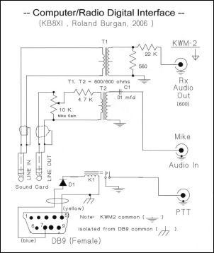
Many thanks to Roland Burgan, KB8XI
who recently sent me this
interface he designed specifically for the Collins KWM-2. He does add
however that it should work an any earlier rig.
Roland is well know in Amateur
circles and has worked with FAR Circuits back in the 90's, for 73 Amateur
Radio, Today Magazine. Remember the following articles? January/1995...Easy
PTT Control; and August/1996...Receiver RF Preamp;
May/1997...Build an Audio Multiplexer for Your Frequency Counter.
If you need further help or
information on this please email Roland at
[email protected]
All parts can be purchased from
Mouser Electronics;
T1,T2 .... part number 42TL016
K1 ..... part number 655-JWD-107-5 (DIP 5/6 VDC SPST-NO)
A printed circuit board can be bought from FAR Circuits. Take a
look at the component list for contact details.
For a complete list of components,
click here. If you would like a printout of this list, simply right click on the popup margin and click print.
|
 |
|
Soundcard Interface - Alinco Handheld DJ-580T |
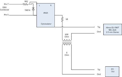 |
Finally for you Handheld
Junkies, Greg Speakman, VA3OMP is sharing his well thought out modifications
and designs for interfacing this radio.
... follows an extract from his email ...
... I was able to connect the 3.5mm (⅛") ext speaker jack, on top of the handheld, directly into the
line-in 3.5 mm jack of the computer's on-board sound card. For the
handheld's combo mic & PTT 2.5mm (1/16") jack, located on top of the
unit, I modified your circuit with the Opto Isolator.
Diagram at left shows the mods.
Regards
Greg Speakman
[email protected]
Many thanks Greg for this fb addition to pc-rig interfacing.
|
| WM2U Tip!! |
I periodically get e-mail telling me that certain parts are no longer available from Radio
Shack. I suggest therefore that you go to the Bux CommCo
Catalog where you get one stop shopping for all your component needs including the hard to get connectors. Oh! by the way Buck sells the sound card,
ISO-KIT and
Little Rascal. Hey! for about $25 you get all the components you need. You can't buy them yourself for that price! Check out the ISO-KIT info here. After reading Bucks' page, go to his Kwik-Select guide
|
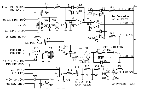
The N9ART Interface
designed by Jim Mitrenga |
Well! you are now really biting at the bit and want to jump
right in there, build a new sound card interface, download that fancy new
windows software and join the Digital Revolution. Hold it! hang loose a minute. Are
you one of those Hams that uses a non-soundcard, serial port type, interface, and you are really comfortable
with that DOS software? You are! well join the crowd.... but you
have realized that there is a problem. Yep! you will get tired of switching
cables from one system to another.
Uhmm! well, I think we have the answer to that for ya!. Lets take a look at Jim's interface. This
interface will give you the best of both
worlds. You can certainly join in the soundcard Digital Revolution and guarantee
clean signals but at the click of a switch you cut the the sound card out
and fetch in the serial port interface that feels and acts just the way
you remember.
Check out the circuit diagram below. err! look familiar? It should. This interface is from an article that appeared in the
November issue of QST, entitled "A Flexible Digital-Mode Interface" and is reproduced by kind permission of the author,
Jim Mitrenga, N9ART.
|
|
 |
For a complete list of components,
click here. If you would like a printout of this list, simply right click on the popup margin and click print.
Ok! the construction of this interface although somewhat more complex than the standard isolated interface, is nonetheless well
within the capabilities of most Hams. All the components can be found at Radio Shack and a ready made PC Board is offered by FAR Circuits at
http://www.cl.ais.net/farcir/
for only $6.00. Since the original QST article can be
downloaded from this site in .pdf format, I will not attempt to cover the
circuit theory or the test and alignment procedure in this write-up. |
Please
download this file and print it off. Jim has made an excellent job of describing
his circuit theory, schematic, construction details, alignment, and the
summary is full of useful links relative to both DOS and Windows
software.
Hey! as Jim said "Now you have no excuse for not trying Amtor,
Fax, Hellscheiber, MT63, Pactor,
Psk31, Rtty, SSTV, et al." For more information you can e-mail Jim at: [email protected]. |
I have operated with most of the modules listed above and have ended up with the Isolated Circuit and both the Opto Isolated versions for RTS and DTR control. That configuration works great in this shack.
After my initial hook-up, and all ground loops removed, I still had problems with RF getting into the computer. I found that winding the cable to the computer speaker system through a Ferrite Core about 4 turns, removed this problem.
However, other Hams were not that lucky. I remember two other cases I was helping with where a Ferrite Core was needed in the Sound Card LINE IN lead and the other was wound in the Keyboard cable before a cure was effected. This process seems hit-and-miss at best so the best approach appears to be one of trial and error.
One very last word but not by
any means the least--- IMD! It is essential that your signal is clean
on the air otherwise you will probably be splattering all over the band. On
all the software available you will see a waterfall indicator which shows
all the PSK traces available to you to work, however yours is NOT
one of them. So how can you see what your signal looks like so you can take
corrective action if needed? Well the other station will help you adjust
your station until you have a fb trace or would you believe, there are
indeed devices available that will allow you to see your own
trace. Check out
PSK Meter by KF6VSG or IMD Meter by KK7UQ.
Got
a soundcard interfacing question? Take a look at this Forum:
http://forums.ham-radio.ch/forumdisplay.php?f=30
To help me collect the different Radio hook-ups please send me this Form
with your Radio's hookup information for publication on this page. Any comments or help would be really appreciated.
I
hope this page grows with the your help and that it is found useful when interfacing you system,
73 de Ernie (WM2U)
|
|