
| RF Power: | 0 to 10, 0 to 100, 0 to 1000 Watts |
| SWR: | Calibrated from 1:1 to 3:1 |
| Impedance: | For 50/52 ohm systems only |
| Frequency Range: | 3 to 30 MHz (Useable at 144 MHz) |
| Connectors: | Coaxial SO-239 (accepts PL-259) |
| Dimensions: | 3 3/8" X 8 1/4" X 4 1/2" (HWD) (8.5 X 21.0 X 11.5 cm) (HWD) |
| Weight: | 29.3 oz (830g) |
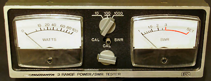
You can read SWR directly on the SWR meter. It is calibrated from 1 to 3, with a red line above 3. When the meter reads 1, the antenna system is perfectly matched to the transmitter and you have an SWR of "1" - or to be more accurate, 1 to 1 (SWR is a ratio). If your reading is more than 3, you should correct the mismatch between the transmitter and antenna system.
You'll note a second set of numbers directly below the SWR value -
these are the "percentage of reflected power" values. Since SWR is the
direct result of mismatch, which produces "reflected waves" (not all
the power is radiated by the Antenna - some of it is reflected back to
the Transmitter) this will give you an idea af the actual efficiency of
your system.
For example, an SWR of 1.5 (more accurately we shculd say "SWR of
1.5 to 1") means 4% of the power is coming back and only 96% of
the available energy is absorbed by the Antenna. An SWR of 2 to 1
means 11% is reflected; and 3 to 1 is 25% reflection.
There are no "percent reflected power" markings on my meter.
NOTE: A "jumper" coax cable such as noted above can be obtained from your local Radio Shack store.
IMPORTANT NOTE: POWER and SWR readings will be accurate only when used with antenna and transmission lines which have an impedance of 50/52 ohms.
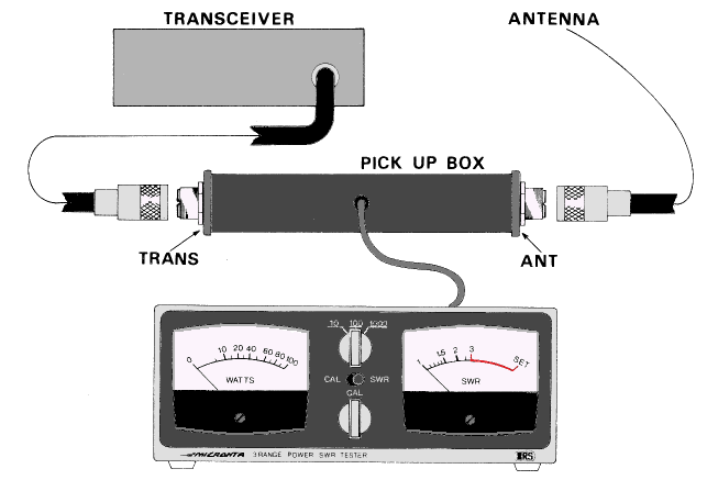
To measure Standing Wave Ratios, set CAL/SWR switch to CAL position. Press the Push-to-talk button on your Mic. Adjust the CAL control for a reading to the SET mark on the Meter. Return the CAL/SWR switch to SWR position and read your SWR on the Meter.
If you have a reading of 1.5 or lower, you have a very efficient antenna system. If the reading is between 1.5 and 3, you may want to try lowering it (although in most cases, an SWR of 3 or less will be acceptable). lf you have a reading of over 3, you should check your antenna system and make adjustments as required to obtain a lower reading.
Adjustments for reducing SWR will depend entirely on your antenna system. We can only give you a few general pointers. Be sure you are using a 50/52 ohm antenna system and cable. Be sure all connectors are secure. Be sure your cables are good (no shorts or deterioration of the cable). If your antenna can be adjusted (see the instructions which come with the antenna), adjust it in small increments. If it is a mobile installation, check to be sure all mechanical connections have been made correctly. Make sure the antenna is vertical; move it away from metal bodies (if possible). For mobile installations, sometimes just a minor change in the positioning or location of the antenna can greatly improve the SWR.

