Broadband Active Loop for Car Roof Use
REV = 20130808
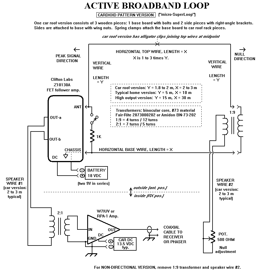
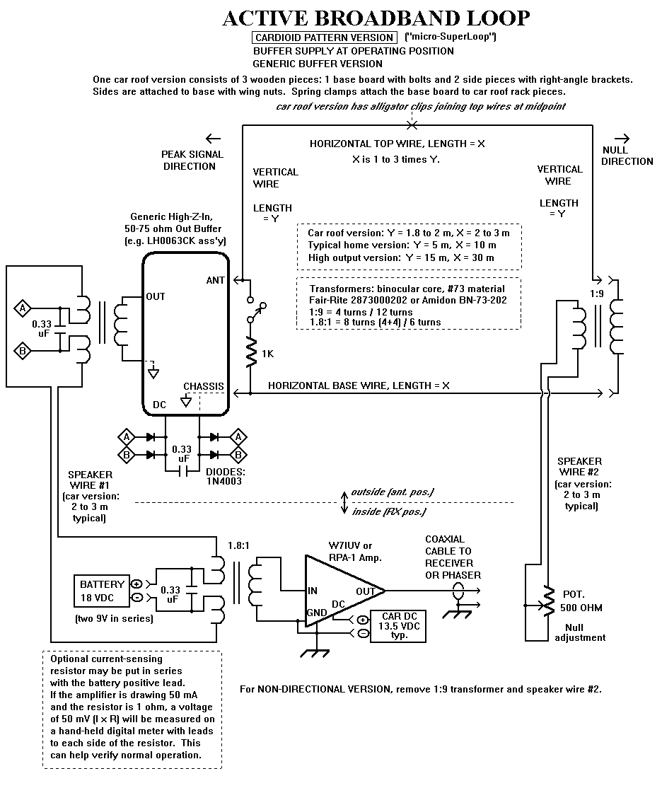
Cardioid pattern version of the antenna is shown in Figure 1.
Figure 1
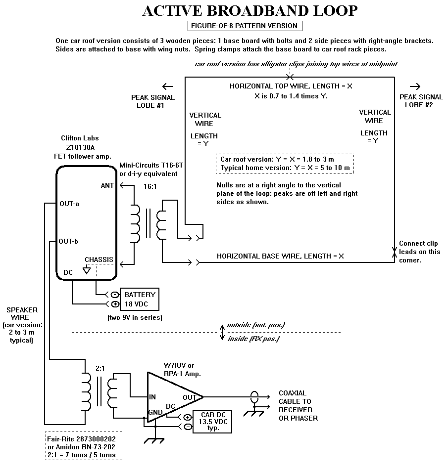
Figure-of-8 pattern version of the antenna is shown in Figure 2.
Figure 2
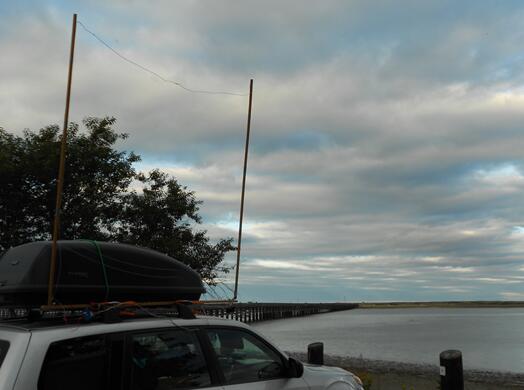
Car roof antenna deployed at Powder Point DXpedition site - Duxbury, MA
Tuned operation for use with ultralight / other portable receivers via inductive coupling:
Connect either the W7IUV amp output or the 2:1 transformer output (instead of sending it to the W7IUV amp) to a short coaxial cable to a plug inserted in the 1/8-inch connector jack of Radio Shack loop model 15-1853 or equivalent. This connection is to a low-impedance winding coupled to the high-Q high-impedance L-C tuned circuit. Place the portable radio near the tunable loop and tune the unit's variable capacitor knob for peak signal. The distance and placement orientation of the radio to the tuned loop for optimum signal transfer will be determined by the user.
Some variations on what is shown in Figure 1
You can maintain the DC power for the buffer amplifier at the operating position by splitting the windings of the transformers used at each end of the feedline from controller to buffer. If diodes are used at the buffer end, there is no need to observe polarity on the feedline connection. Since the battery is not referenced to station ground, there is little likelihood of noise being injected. One could operate the post-amp (W7IUV or RPA-1) from the same DC source but then a 1:1 transformer might be needed en route to the receiver or phaser to keep the grounds isolated. You would likely need a higher current battery than the two series 9 volt ones. Rechargeable batteries used for hand tools and laptops often can supply 16 to 19 VDC so those may be usable.
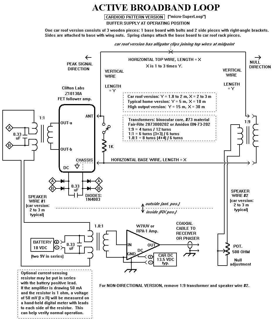
Operating-position-sited-battery version of cardioid pattern antenna with Clifton Labs buffer is shown in Figure 3.
Figure 3
Other generic buffers that are high-impedance-in to single-ended 50 to 75 ohms out can also be used. These include the BUF-B amplifier used in the DXP-1 phaser; it's similar to that used in the the MFJ-1024 whip. The amplifier of the PA0RDT mini-whip could also be used. Several other possible buffer amplifiers are found on the Buffer Amplifier Links Page.
Operating-position-sited-battery version of cardioid pattern antenna with a generic buffer is shown in Figure 4.
Figure 4
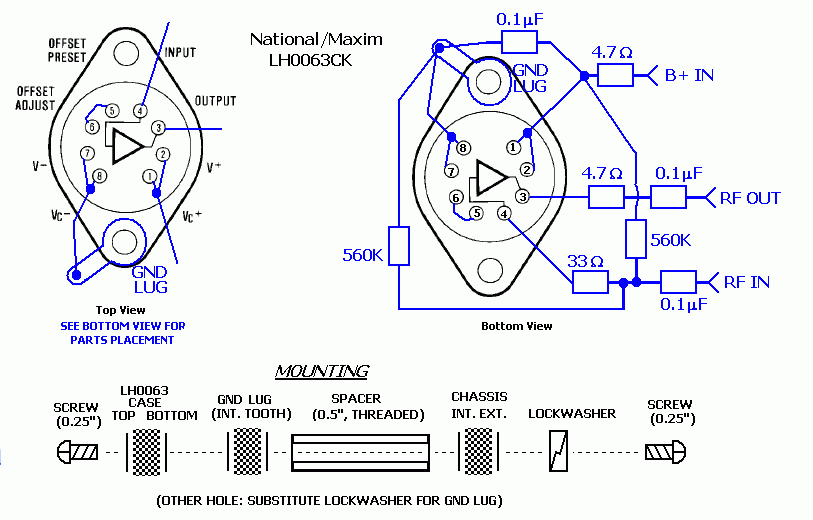
Since I have a flea-market stash of (now-obsolete) LH0033G and LH0063CK buffer chips, I sometimes use them since they are relatively low noise.
A generic buffer using an LH0063CK is shown in Figure 5.
Figure 5
APPENDIX
Test notes: 8 AUG 2013
I installed a Micro-SuperLoop antenna under the back deck of my house (South Yarmouth, MA). This was strictly for equipment testing purposes as it is too close to home-based broadband RF noise sources to be of any use for DXing. The antenna measures 1.7m (5.6 ft.) vertical by 3.6m (11.8 ft) horizontal. The base of the antenna is 0.3m (1 ft.) off the ground. It is on an east-west axis.
Since there is only one meaningfully-strong daytime signal to the east (1170 WFPB: Orleans, MA), I did strength testing with the antenna feed from the west end and with the east end terminated, putting WFPB in the cardioid null and a variety of westerly stations in the forward lobe so gain could be assessed at several frequencies.
Stations observed in the midday groundwave tests were 660 WFAN (NY), 880 WCBS (NY), 1050 WEPN (NY), and 1480 WSAR (MA).
Reference readings were taken with the lowest gain, completely passive, situation of a 9:1 transformer at the antenna feedpoint, the 5m (16 ft.) speaker wire feed to the basement operating position, and a 2:1 transformer to the Perseus receiver coaxial feed.
Situations providing gain were then employed.
Set-up A = W7IUV amplifier after 2:1 transformer and ahead of receiver:
Set-up B = antenna-sited Clifton Labs Z10130A buffer (instead of 9:1 transformer) to feedline to 2:1 in-shack transformer to receiver:
Set-up C = Clifton Labs Z10130A buffer (as above) to feedline to 2:1 in-shack transformer to W7IUV amplifier to receiver:
It was not possible to judge noise figure since house and powerline based electrical noise exceeded amplifier noise across the medium wave band. Noise floor evaluation would have to be performed during the day at a field site. In normal sunset skip and evening operations at beach DXpedition sites, ambient band noise (static, splatter, etc.) always seems to exceed whatever the buffer and post-amp are creating. Daytime (or night DXing in a more remote part of the world) at a really quiet site could be another matter.
Future tests may include other at-antenna buffers and at-receiver post-amps.
Amplifier description links:
Other links:
BACK TO RF CIRCUITS MAIN PAGE