A Portable Antenna for Mode B and J Satellites
While I've made a point elsewhere that amateur satellites can be worked with minimal gear, if the satellite and conditions are right, having an antenna which is better than the typical rubber duck or shack vertical can enhance one's enjoyment of this fascinating aspect of Amateur Radio. In my case, I had been working SO-35 with a 1/2 wave on 70cm and a 1/4 or 5/8 wave on 2m. With these antennas and a little planning, it is possible to work this bird from a train! However, not all passes are created equal, and there are also other satellites to work. For example, UO-14, which was recently reconfigured as an FM repeater, after many years of data service, or the Fuji birds, FO-20 and FO-29. It is difficult (though I have done it) to work UO-14 on the antennas I used for SO-35, and even more difficult to work FO-20 this way. To access these birds, I needed better antennas. After a bit of hunting around on the Internet, I came up with what I thought was an easy to construct, yet effective portable antenna.
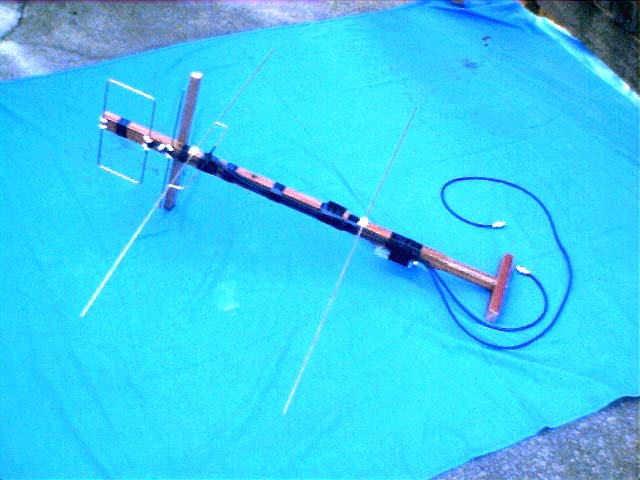
On 70cm, the Texas Potato Masher, designed by Jerry, K5OE, looked quite good. On later experimentation, I discovered I didn't nead the circular polarisation, as with a portable antenna, one can manually rotate the beam on its axis to eliminate polarisation errors, so I only used one loop of the TPM II design, which I will call the "Linearly Polarised TPM II", or LPTPM II, for short. I didn't bother with impedance matching and decided that the performance, even with the expected 2:1 VSWR mismatch was excellent. Terrestrial tests on repeaters and simplex, as well as on air tests on UO-14 showed this antenna to be an excellent performer all round.
For 2 metres, I ended up going for a 2 element Yagi, using the well known DL6WU program to calculate the measurements. The driven element is fed by a T match, which is soldered in place - again I favoured simplcity and ruggedness over electrical perfection. The Yagi is mounted at 90 degrees to the LPTPM II on the same boom, and just behind it, to minimise interaction. However, there is the option to add a third element to the Yagi if a little more gain is required. The third element would go through the middle of the loop of the LPTPM II.
Construction of this antenna should present few problems. The antenna is made out of 3 mm thick brazing rod, which was obtained from a local welding supply shop. This material is easy to work with and solder. For the LPTPM II, I used the dimensions given on Jerry's site. The loop is 107.5 mm by 240 mm, with a gap of 10 mm being left in the rear "long" side of the loop to attach the feedline. The reflector is 336.5 mm long, and is mounted 50 mm behind the loop.
For the 2m Yagi, the reflector is 1007 mm long. This meant soldering two lengths of brazing rod together, as the lengths were only about 750 mm long. The driven element is 972 mm long (again, solder 2 lengths together!), and is mounted about 40 mm behind the LPTPM's reflector and at right angles. The reflector is positioned 380 mm behind the driven element.
The feed is a T match. The arms of the T connect to the driven element 115 mm each side of the centre point of the driven element. A 4:1 balun, constructed out of a 1/2 wavelength of RG-58 coax is used to couple the T match to the 50 ohm feedline.
Optionally, a director of 931 mm length can be added 162 mm in front of the driven element (if the antenna is constructed as described, it should pass through the centre of the LPTPM II's loop). I haven't installed the director on my antenna, the 2 element Yagi works quite well as it is.
Drawings with dimensions are shown below for both the 2m Yagi and 70cm LPTPM II.
Performance:
The LPTPM II has been tested extensively on UO-14 and terrestrial paths. It is capable of receiving the satellite's downlink practically from horizon to horizon, and despite the relatively weak downlink, it is possible to hear the downlink well before being able to access the bird with a couple of watts into a 5/8. On most passes, the LPTPM II will hear UO-14 from horizon to horizon with few fades. The 70cm antenna can also receive FO-20's beacon down to the horizon, even with a few dB of coax loss between it and the receiver, and from a very poor location.
The 2m Yagi has only recently been added and shows much promise. Tests through FO-20 with 2 Watts power gave a strong return carrier on the downlink, strong enough to be full quieting on an FM receiver. 1/4 W on the uplink gives a noisy carrier on the FM receiver, and certainly enough for an SSB or CW contact (Anyone for QRP? :) ). Unfortunately, the HT I was using on 2m has a "sloppy" button, so I was unable to attempt a CW contact (my attempt was very QLF!). However, any CW I sent would have been rock solid into the bird. I need to build another transverter for the 10m box before I can work SSB through FO-20, though HT sent CW is always a possibility. ;-)
For those people who are stuck in a unit or apartment, there is no excuse not to work satellites, as this antenna is portable, and you don't need much power into it to get good results.
Anyone looking for a demonstration of this antenna's performance is welcome to download the audio tracks below from UO-14 and SO-35. The audio was recorded off the downlink receiver, i.e. exactly as I heard it off the beam.
UO-14 - This was a 50 degree elevation pass. Note the stability of the downlink signal. My 2m uplink was 2 watts. Most of the stations present were having difficulty hearing the downlink.
SO-35 - Taken from a 40 degree elevation pass. Uplink power was 3.5 watts, except for a brief, announced test at 0.5 W!
![]()
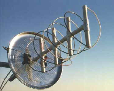
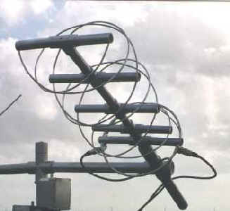
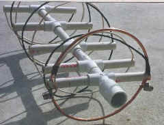
The first prototype (left) was built with a solid 15" aluminum (pizza pan) reflector. That design proved to be frustratingly difficult to match to 50 Ohm feedline. Having nothing to lose and everything to learn, I opted to dump the reflector and re-constructed the antenna using an AF9Y design tuned ring reflector (right). It worked well. The first time.
As I make plans for P3D, one of the big projects I have yet to finalize is a 2.4 GHz downlink. My Drake 2880 downconverter is sitting on the shelf ready to be converted. All I need is an antenna. There are many options, but none seem to be as well suited as a helix (axial mode helical antenna). Primary among the desirable attributes of this antenna are its simplicity of construction and it's wide bandwidth. The former appeals to the mechanic in me and the latter appeals to the practical knowledge that at 2.4 GHz, forgiving construction tolerances are required for me to be successful.
There are many fine designs already developed and you can find them in the literature and on the Web (e.g., see the G3RUH design and the W0OQC design). All of these designs, however, assume a fixed circular polarity, usually right-hand (RHCP). Since P3D is an unknown, I am leery of committing to a physical design with a fixed circular polarity--I feel I would be safer with a fixed linear design. Without getting into the debate about linear v. circular polarity, my real-world experience on both the LEOs and with AO- 10 have convinced me there is no such thing as fixed polarity from a satellite (at least not at the ground station observer's viewpoint) and having the ability to switch circular polarities is very, very desirable and effective. I want to stay away from the linear Yagi and loop-Yagi designs (at 13 cm) because of the expectation I could not reproduce them accurately enough. Pondering this conundrum is where I got the idea to put two helical antennas on the same boom--hence a double helix (of the non-biological variety). One helix is wound to be RHCP and the other is wound to be LHCP. I start them 180 degrees out of phase and only one is "active" at a time and the other one "floats."
Design:
The classic formulae at the right are conveniently available in a number of shareware programs. I used HELIX5 from VK5PGT and designed the following antenna:
| Frequency | 436 MHz |
| Axial length | 17-1/4" |
| Turn Spacing | 5-3/4" |
| Helix Diameter | 8-5/8" |
| Pitch Angle/FONT> | 12 Deg. |
| Length of Wire | 27-11/16" |
| Gain | 11.6 dBi |
| Beamwidth | 65 Deg. |
| Impedance | 140 Ohms |
Construction:
My first check of the SWR indicated 2.5:1. This was much better than the solid reflector. I "played" with the spacing and found by elongating the first turn's spacing slightly, I could get very close to 1.0:1 SWR with no further adjustment and a very broad response: the 2:1 SWR points were 424 MHz and 452 MHz! The final dimensions turned out to be 2-11/16" from the reflector to the 180 degree point of the first turn and then 4-3/16 for the remaining 180 degrees (to the start of the second turn). The second and third turns were left at the nominal 5-3/4" separation. I found many combinations of dimensions would yield a good SWR, so more exacting test-range measurements or modeling is in order to fine-tune this method for the best gain.
The ring reflector is made from 1/4" copper tubing and is 9" in diameter (5% more than the helix). Notice in the photos how the UHF connector is mounted behind the reflector support pipe and the helix wire comes very near the reflector before attaching to the center pin. This first 2" of the helix is very sensitive to adjustment and 1/8" movement can affect the feedpoint impedance significantly. Trial and error. The two helix are each fed to one side of a coaxial relay for switching between RHCP and LHCP. I found if I grounded the un-used helix, the SWR of the selected helix would rise to about 2.5:1, so I left it floating.
 |
   |
|
| Assembled Unit | > | Ring Reflector / Coax Connector |
Findings:
I had the antennas shown in the photos mounted in place of my venerable TPM
II for several days of empirical testing and observation. Mounting the
antenna at an estimated 30 degree elevation, testing entailed having phone QSO's
on four different amateur satellites. Here is what I found:

Gain:
I tested the prototype with a field strength meter against my 70 cm Handi-Tenna, a known 9-10 dBi design. The prototype appeared to have just about the same gain (which is slightly, maybe 1 or 2 dB) less than the previous version with the solid reflector). In on-the-air comparisons, it appears to have less gain, at least 3 dB, than my usual antenna, the TPM II.Size:
This antenna is still larger than my 2 meter TPM II (see photo at right), a design of comparable gain and polarity flexibility, but is significantly smaller and lighter without the solid reflector. Make no mistake, these are LARGE antennae for their effective gain! This antenna is still many times larger in wind load and much heavier than the TPM II.Pointing: This was a casually constructed, experimental model. The first prototype had an error in the winding of one of the loops, explaining the odd off-pointing behavior I observed (sorry). This new design (with correct winding) appears to have good axial symmmetry.
Performance:
Next Steps:
I don't plan on pursuing a 70 cm design any further. I plan to model this version first to confirm my findings, extrapolate the model to a longer version of this basic design, with perhaps a tapered profile (more gain), and then scale the design to 13 cm. My next helix construction project will be a mode S downlink antenna for P3D. See you on mode U/S.