![]()
ELEMENTARY THEORY OF ELECTRICITY & MAGNETISM
What is electronics?
Electronics is the field of manipulating electrical currents and voltages using
passive and active components that are connected together to create circuits. Electronic
circuits range from a simple load resistor that converts a current to a voltage, to
computer central processing units (CPUs) that can contain millions of transistors. Electronic
devices operate by the movement of electrons through conductors, e.g. wires, and
electronic components.
What are passive components?
Resistors,
inductors, transformers and capacitors are called passive devices. They don’t
alter their resistance, impedance or reactance when alternating currents (ac) are applied
to them.
What are active components?
Vacuum tubes, diodes, transistors etc. are called active devices. They change their
resistance or impedance when varying voltages are applied to them and as a result can
amplify, rectify, modify or distort ac waveforms. Passive devices normally don’t
distort waveforms.
Matter and electricity
Before going to discuss
the different theories related to electricity and magnetism, we would like to give a brief
idea about matter. All matter consist of molecules. A molecule can be defined as the
smallest particle, which shows all the characteristics of a particular matter. For
example, molecule of water is obtained by dividing a drop of water again and again until
it can be divided and still be water. Further division of this water molecule will yield
three particles which are not water. Molecule of water contains two atoms of hydrogen (H)
and one atom of oxygen (O). Chemical combination of different atoms makes a molecule. An
atom can be further divided into three particles known as protons and electrons and
neutrons. Protons and electrons are the particles possessing electrical properties whereas
neutron is electrically neutral. These particles can't be divided further.
Electrons are the
negatively charged particles, which revolve around the positively charged protons
(which constitute the nucleus of an atom along with neutrons). Proton is about 1800
times heavier than electron. There is always attraction between unlike charges.
Because electron is much lighter than proton, hence it is pulled towards the proton. If
the force of attraction is enough, then the electron comes too closer to the proton and
both the particles together form a neutral particle to be known as neutron. Atoms,
of all matters, except hydrogen contains one or more neutron in their nucleus.
Though electrons and protons have different kind of charge in them, both have charges of
equal magnitude. An electron (negatively charged) repels another electron, while a proton
(positively charged) repels another proton. So
the basic physical law states:
"Like charges repel; unlike charges attract."
What is charge?
Charge is an amount of electrons. Its unit is coulomb (C) and
symbol is ‘q’. One coulomb is equivalent to 6 x 10¹⁸ electrons.
Atoms of
a metal form a crystal lattice, and in the spaces between the lattice points free
electrons move chaotically, wandering aimlessly here and there. But it is enough to
connect a metal plate to the two poles of a voltage source for the electrons immediately
to acquire an aim. They will move towards the positive pole of the battery, and an
electric current will begin to flow in the metal. An electric current can also flow in a
gas. A voltage applied across a gas-filled tube causes ionization of the gas: free
electrons stream towards the plate with the positive potential, colliding with the atoms
in their way and detaching electrons from their orbits. The positive ions move toward the
opposite end of the tube. Current is the rate of flow of charge, i.e., the number of
coulombs flowing past a point per second. Its unit is ampere (A) or amp. One amp is equal
to one coulomb per second.
What is voltage?
Voltage is also called potential (Potential is defined as the work required from some
energy source in moving a unit positive charge between two points in an electric field),
potential difference, potential drop, or electromotive force-EMF. It is the electronic
potential energy between two points, and is the driving force that causes charge to flow.
Its unit is volt (V). One volt is defined as the potential difference that requires one
joule of energy to move one coulomb of charge. Voltage is always measured relative to some
other point in a circuit, e.g. the potential across a resistor. Voltage measurement made
at a single point in a circuit are made relative to the earth (ground), which is assigned
an “absolute” voltage of zero.
Types of electricity:
Direct Current (DC):
The current, which flows in one direction in a circuit. DC voltage has a fixed
polarity (e.g. a battery or an electrical cell) and the magnitude of the current remains
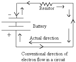
constant. In an electrical circuit, the flow of electric current is indicated by an arrow
mark originating from the positive terminal of the battery towards the negative terminal
of the battery. This is the conventional method of showing the direction of current flow.
But the real direction of electron flow is
Alternating Current (AC):
Alternating current flows first in
one direction then in the opposite direction. The same definitions apply to
alternatingvoltage. AC voltage switches polarity back and forth. AC voltage/current
has a wave-form which represent the frequency of the source. The wave-form of the
household ac is known as the ‘sine’ wave. The magnitude of the A.C. voltage
changes with time. AC is obtained from A.C. generators.
Advantage of A.C. Heat is developed in all type of
electrical circuits due to the flow of electric current. The magnitude of the D.C. being
constant produces more heat in a circuit compared to the heat produced by an A.C. In long
distance transmission lines, large amount of power will be dissipated in the form of heat
if D.C. is used which can be reduced by the use of A.C.
Magnetism:
What is a magnet?
A piece of iron, nickel, cobalt, steel, alloy (e.g. alloy made
from non-magnetic copper, manganese and aluminum) etc. usually in the form of a bar having
properties of attracting or repelling iron is called a magnet. But what gives it its force
is not completely known. One of the theories to describe magnetism is the-"Theory of
Domains". It says that materials that can be made into magnets have many tiny crystal
like structures called domains. Each domain is made up of many atoms. Each domain has a
small magenetic force of its own. When the material is not magnetized, the domains are
haphazardly arranged-pointing in all directions-so that their tiny forces cancel each
other. To make the material into a magnet, the domains need to be lined up so that their
individual magnetic forces all help each other pull the same way. When most of the domains line up, the magnet becomes strong. When all of
the domains line up in one direction, the magnet is saturated. It cannot be made any
stronger regardless of how much you try to magnetise it. In a magnetic bar, there are two
poles: North and South. They are marked as ‘North’ and ‘South’ poles
because, when the magnetic bar is suspended horizontally, one of the ends will always
point towards the Earth’s geographical north and the other pole towards the
Earth’s geographical south. This is because of the fact that the Earth itself behaves
like a huge magnet. In a magnet, the like poles repel and the unlike poles attract-a
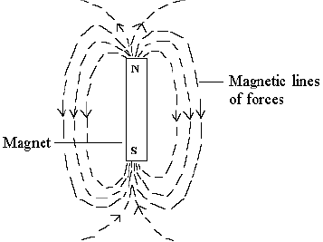
reason for the specific alignment of the magnetic bar. The magnetic bar is surrounded by
the invisible lines of forces which originate from the ‘North’ pole and
terminate in the ‘South’ pole.
Ferro-magnet:
iron, nickel and cobalt (including the alloy mentioned above) are considered
ferromagnetic. Ferro-magnetic materials are difficult to be converted to magnet but once
magnetized under the influence of another magnetic field, they cannot be completely
demagnetized. Ferromagnetic materials are used to make permanent magnets. One of
the strongest permanent magnets is a combination of iron, aluminum, nickel and cobalt
called "Alnico".
Materials which get demagnetized once the external
magnetic field is removed are paramagnetic.
Use of Permanent magnets in Electronics:
Permanent magnets are used in electronics to make
electric meters, headphones, loudspeakers, radar transmitting tubes etc.
What are resistors?
Resistors are load elements that dissipate current into heat.
They are used in circuits to adjust voltages. Resistance (R) is the retarding force in a
material that impedes the flow of current. The potential (E) needed to achieve a current
(I) through a material that behaves linearly, e.g. conductors and resistors, is given by
Ohm’s law:
E=IR
Where E=emf (in volts, V)
I=intensity of current (in amperes,
A)
R=Resistance (in ohms, W )
So, if we know any two values, we can find out the other
value. The above formula can rearranged as shown below:
From this formula, it is evident that-"Current varies directly as the voltage and inversely as the resistance".
The formula can also be arranged to find out the resistance in
a circuit if the voltage and current are known.
R=E/I or Resistance in ohms= volts/amperes
Practical Resistors:
The resistance of a material depends on four physical
factors:
(1) The type of material from which it is made. For example copper and silver are very
good conductors of electric current, but iron is six times lesser in its conductivity than
them.
(2) The length (greater the length greater is the
resistance).
(3) Cross-sectional area (greater the
cross-sectional area larger the amount of free electron implying lesser resistance).
(4) Temperature (except for carbon and other semiconductor
materials).
So each material has a specific resistance inherent in them.
The specific resistance of a material is the number of ohms in a 1 foot long 0.001 inch
diameter round wire of that material at room temperature. Silver has the least specific
resistance, i.e. 9.75 W and nichrome is an alloy, which has specific resistance as
high as 660 W.
Wire-wound resistor:
Nicrome or german silver wires are wound on a tubular
ceramic form to make wire-wound resistor.
Carbon resistor:
Powedered carbon is mixed with a binding material and
baked into small, hard tubes with wire attached to each end to make carbon resistors. The
percentage of carbon in the mixture determines the resistance value in ohms.
Colour codes of resistors
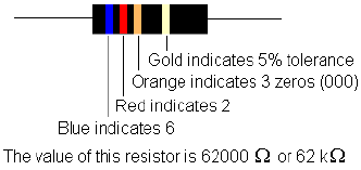
Carbon resistors are colour coded to indicate their
values. Each resistor has four colour bands on its body. The first band (the band which is
nearest to the end of the resistor) is the first number. The second band is the second
number. The third band is the multiplier, i.e. number of zeros following the second
number.
Resistors having values lower than 10 W have three colour bands. The third band is either golden or
silver in colour. A golden band indicates that the first two numbers are to be multiplied
by 0.1. A silver band indicates multiplication by 0.01. The tolerance of three band
resistors is 20%. If the golden or silver band is the fourth band respectively, then they
indicate a tolerance of 5% and 10% respectively.
Colour |
Band1
|
Band2
|
Band3
|
Black |
0 |
0 |
|
Brown |
1 |
1 |
0 |
Red |
2 |
2 |
00 |
Orange |
3 |
3 |
000 |
Yellow |
4 |
4 |
0000 |
Green |
5 |
5 |
00000 |
Blue |
6 |
6 |
000000 |
Violet |
7 |
7 |
0000000 |
Gray |
8 |
8 |
00000000 |
White |
9 |
9 |
000000000 |
Questions:
1. A
circuit has a resistance of 100 ohms and voltage applied across the circuit is 20 volts.
What is the amount of current flowing through it?
We have, IR=E or 3 x 50 = 150 V
(volts)
As mentioned above, heat is developed in the load resistor as a
result of current flowing through it. In absence of the load, a battery despite having the
electro motive force (EMF), cannot produce movement of electrons and no electrical work is
accomplished. When there is a load across the battery, movement of electrons take place.
The product of the EMF (in volts) and movement of electrons (in amperes) gives us the
amount of electrical work accomplished whose unit is watt (W).
E=emf (in volts, V)
I=current (in amperes, A)
So, 1 V causing
1 A to flow through a 1 W resistor produces 1 W of power.
The above formula can also be expressed as
Or
P=EI=E(E/R)=E2/R (because the ohm’s law states: I= E/R)
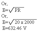
1. Find out the heat dissipated by a 50 W resistor when 0.25 A of current flow pass through it.
We have, P= E2/R
Or , E2=PR
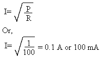
4. Find out the maximum current that can flow through a 100 W 1 W resistor.
We have,
What are conductors?
Matters which allow the flow of electric current through them are called conductors. Metals are known to be good conductors, with copper and silver among the best. The conductivity of a particular material depends on the number of free electrons present in it. A conductor may be a very good conductor, a fairly good conductor or a poor conductor. So, a greater conductivity or conductance implies lesser resistance and a lesser conductivity implies greater resistance. So, conductance (conductance is expressed in siemens, S) and resistance (R) are the same thing but from opposite viewpoints. They are said to be reciprocal of each other, i.e.
R=1/S or S=1/R
So the Ohm’s law can be
expressed in terms of conductance by using 1/S in place of R in the three foremulas:
E=IR=I(1/S) or E=I/S

Resistance in series and parallel
The circuit in Fig1 is a simple circuit with one load or resistor across a voltage source (e.g. a battery)

The circuit shown in Fig 2 is a series circuit where three resistors are
connected one after another and as evident from the diagram, there is only path through
which current flows.

The circuit shown in Fig 3 is a parallel circuit where each resistor has its
independent path for the flow of current from the same source of voltage.

The circuit shown in Fig 4 consists of two batteries and three resistors in series. In a series circuit the same amount of current flows through all parts of each circuit. The resistors are connected in series to obtain a greater resistance and it is equal to the sum of the values of each resistor, i.e. 40 W. Two batteries are connected in series in this circuit to obtain the highest possible voltage which is the sum of the values of each battery, i.e. 20 V.

From the Ohm’s law, the
current flowing through this circuit will be:
I=E/R or I=20/40=0.5 A
We
should be careful while connecting batteries in series, because, the maximum current
possible through the circuit is no greater than the greatest current that the weakest
battery can deliver. If one of the batteries in the above example is weaker than the other
and capable of passing only, say, 0.2 A, it will be overworked, may overheat and the
voltage across the terminal will drop.
In this type of circuit, the voltage that can be obtained across each resistor is called the ‘Voltage drop’. From the Ohm’s law, the voltage across each resistor can be calculated. The voltage drop across the 30W resistor is 15 V (0.5 x 30) and the voltage drop across the 5W resistor (each) is 2.5 V. Thus the sum of the voltage-drops is equal to the source voltage (2.5+2.5+15=20V).
Internal
Resistance of batteries
The battery might possess an internal resistance which is to be considered while
calculating the various quantities in a circuit. If a 10 V battery has 1W internal
resistance and connected across a 9W load
resistor, the amount of current flowing through the circuit would be 1 A. A voltage drop
of 1 V will take place inside the battery and hence the 10 V battery will produce only 9 V
across its terminals when connected to the 9W load. When
the circuit is open (no currents flowing through it), the voltage across the battery would
be 10 V.
Resistors in parallel circuit

The circuit shown above is a circuit where two resistors are connected in parallel across the voltage source. Obviously, there are two paths for the flow of current. One part of the current flows through R1 and the other part flows through R2. Since total conductance St of a circuit is equal to the sum of all the conductances connected in parallel, the formula can be expressed as: St=S1+S2
Or St=1/R1+1/R2
Or 1/Rt=1/R1+1/R2
The above equation is made into a pair of fractions by placing a 1 over both sides,


The circuit shown above seems to be a complex circuit. By looking at the arrangement of the resistors, their values can be computed in simple steps. As indicated above, calculate as per the steps shown [e.g. step (a), step (b)…..]
Step (a): 15W & 5W resistors are arranged in parallel imparting a value equivalent to 3.5W
Step (b): 3.5W+ 20W=23.5 W (arranged in series)
Step (c): 6.67 W (arranged in parallel)
Step (d): 23.5W & 6.67W are arranged
in parallel or the equivalent value
What are insulators?
The materials which do not allow the flow of electric current through them are called
insulators. Glass, porcelain, dry air and dry wood are well known insulators.