PCBs, Kits & Assembled Units are Available NOW!
Dealers & Stockists Required Outside INDIA. Please Contact.

Download Receiver Schematic Diagram
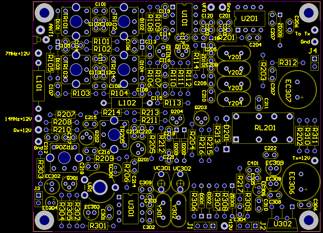
Receiver section consists of two Band Pass Filters (for 7MHz & 14MHz) tuned to the Mid-Band i.e., 7.05MHz and 14.175MHz respectively. TR1 & TR2 are meant for one band and TR3 & TR4 are meant for the other band. TR1 consists of 2 turns in the Primary and 32 turns in the Secondary. TR2 consists of 32 turns in the Primary and 5 turns in the Secondary. TR3 consists of 2 turns in the Primary and 16 turns in the Secondary. TR4 consists of 16 turns in the Primary and 5 turns in the Secondary. All the four TRs are wound with 36SWG enameled copper wire. The incoming signal is amplified by a 2-stage broadband RF Amplifier made of 2N2369 general purpose transistors. This signal is fed to a SA612 Mixer IC which gets the Local Oscillator input from the VFO Board. The resultant 10MHz IF is then passed through the ladder filter made up of four 10MHz crystals. This IF signal with a bandwidth of roughly 2.5kc (SSB Bandwidth) is further amplified by a 2-stage IF Amplifier made up of 2N2369 transistors and TR5 & TR6 tuned to 10MHz. TR5 & TR6 consist of 20 turns in the Primary and 5 turns in the Secondary, wound with 36SWG enameled copper wire. This amplified 10 MHz IF signal is mixed with a BFO (Beat Frequency Oscillator) made using another SA612 Mixer IC which also works as a Product Detector. The audio amplifier consists of a TDA2003 IC connected to a 4 - 8 Ohm 5Watt speaker. There is also an AGC stage before the audio amplifier.

Download Receiver Layout Diagram
The Receiver PCB also houses a part of the transmitter section as some of the stages like the RX Mixer and the IF stages are also used in the transmitter preliminary stages. The Mic Amplifier consists of a single stage amplifier made using 2N2222A transistor. The human voice (speech) is amplified to the desired level to mix with the BFO consisting of LSB & USB crystals in the SA612 Mixer IC that is being used as the Product Detector in the Receiver side. During the transmit cycle, all power is removed from the Receiver stages and hence the SA612, during the transmit cycle, works as a Balanced Modulator. Once the desired side band modulation passes through the IF Filter it is mixed with the Local Oscillator signal to produce the desired output frequency. The mixer used for this purpose is the same SA612 Mixer IC that is being used in the Receiver.

Downoad RX PCB Image
Downoad Bill of Materials text file for the RX PCB
You are visitor number
Return to Home Page
Email: Jagdish, VU2JH