by Pradeep VU2PEB
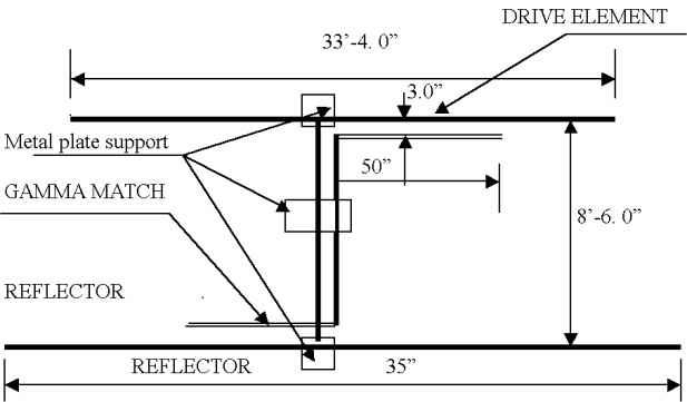
Fig I
by Pradeep VU2PEB
Fig I
I am using the two-element beam described here for the past two years and I
have been able to contact several DX stations getting 5-9 reports. I was
able to obtain DXCC award from ARRL using this beam and I would strongly
recommended this beam for those interested in DX operation.
I was able to get DX station even during daytime. This beam is more compact
and much easier to build and uses minimum of parts. The main advantage is
 that the length of the Boom length 8’-6. 0”in conventional beams it will
 be much higher.
Fig I shows the construction of the boom and the supporting shaft.
Both are made of GI pipes. � inch diameter .The vertical pipe is welded
to the boom at the center. At the two end of the boom a plate about 5-inch
length and 1.6 inches wide is bent in to the form of an arc welded.This is
to clamp beams to the boom.
The construction of the beam are also shown in
this figure for the beam we use aluminum pipe of � inch, 5/8 inch and � inch
diameter-the smaller on sliding into the larger tube .The tubes are fixed by
screws but this should be done after turning. The elements are fixed to boom
using hose clips or pipe clamps .
The construction of the Gamma match is the most critical part and should be
done with care. There are two Gamma matches which are exactly identical and
mounted on each beam on opposite sides as show fig 2. For making the Gamma
match we use an aluminum tube 3/8 inch diameter which is 50 inches long .
The aluminum tubes is fixed to the main beam with two clamps. The inner one
is made of Hylam. The outer is an aluminum clamp that makes connection with
the beam .You can use a strong brass clamp also. Take a piece of RG 213 or
RG 8 cable and remove the outer braid. Only the inner conductor and
insulation will remain. This is slide in to the tube and acts as a capacitor
between the transmission line and the beam. A small metal plate with a hole
to accommodate SO239 socket is welded to the boom as shown.
One end of RG213 cable is soldered to center pin of SO239.By sliding the
tubes you can alter the capacitance between the cable and the beam. After
mounting the two  Gamma matches on either side, connect them together with
a stiff of copper wire as shown. This is copper wire should be kept about
 3 inches away from the boom. The transmission line should be connected to
the socket near the driven element.
The Gamma match [Fig 2] tube should be mounted 1 � inches away from the beam.
Use SWR meter to adjust the Gamma match for SWR equal to one.
The beam should be kept at a height of 6 meter above ground while turning.
For correcting the sliding contact. Adjustments of the Gamma match will
have to be done one both side equal one at 14.3 MHZ you will have to
adjust length of the smallest tubes on the beam to
get correct SWR at 14.2 Mhz.

73 & good DXing