Last updated: August 9, 1999
This Wire-J is an easy to make, light weight temporary antenna with good performance. I do not know how to verify its maximum usable power, but find no problem with running power within legal limit to 2M and 6M versions. I like to bring it along as a backup antenna when I go camping or expedition. I constructed it from 300 Ohm Twin-Lead (Ribbon Type) flexible line. The material cost is close to nothing. With a little planning before you cut the twin lead, you can easily make TWO antenna at a SINGLE cutting job!

| AB = 0.5 * c/f * vf1
c = velocity of light ( 299,792,458 m/s ) f = centre frequency of the antenna in Hz vf1 = velocity factor of coated wire (I use 0.95) (This radiator uses just one leg of the twin lead extended from BDEG) | ||
| BD = EG = 0.25 * c/f * vf2
vf2 = velocity factor of twin lead used (for commonly available 300 ohm twin lead using polyethylene as dielectric it should be 0.82, there is also another less common type using different dielectric which I prefer and its VF is 0.85 ) | ||
| CD = EF
about 2.1 cm for 2M (50 ohm) about 6.3 cm for 6M (50 ohm) I do not know how to calculate, just by trial and error. |
| Tuning | ||||
| 1. | Cut AB to exact size.
| |||
| 2. | Cut BD and CD so that they are 10 to 15% longer than calculated size.
Leaving additional 2cm of stripped conductor at D and E.
| |||
| 3. | Use coaxial cable like RG58 to feed the antenna at C,F. Connect the centre
conductor to C and the braid to F. Make a decoupling loop by making
a 4 turn coil, 2 to 5 inches in outer diameter close to the feed points.
This loop can also serve as a balun (This antenna design expects balanced feed).
| |||
| 4. | Short the stripped conductor at D, E (mentioned in 2) together.
| |||
| 5. | Hang up the antenna by fishing rode or PVC tube in an open area (more than half
wavelength clear of surrounding objects and ground). Feed the antenna by either
a transceiver with a VSWR meter or by a SWR analyser (like MFJ-259). Check the
frequency with lowest SWR reading (center frequency) and its resistance value
(if using an analyser with resistance reading). Record the center frequency,
SWR reading and, if possible, the resistance.
| |||
| 6. | IF center frequency is BELOW the designed frequency AND resistance is ABOVE the resistance (usually 50 ohm) needed: IF NOT, SKIP THIS STEP!! Trim CD and EF by 2mm steps. Remember leaving addition 2cm stripped conductor and shorting D,E together again after trimming! | |||
| 7. | IF center frequency is BELOW the designed frequency AND resistance is EQUAL TO OR BELOW the resistance (usually 50 ohm) needed: IF NOT, SKIP THIS STEP!! Trim at BOTH A & G by 2mm steps. Trimming them together is to keep the length of the radiator AB unchange! | |||
| 8. | IF center frequency is ABOVE the designed frequency: IF NOT, SKIP THIS STEP!! The antenna is over trimmed. You either have to accept higher center frequency (You have to change the length of AB too!) or start everything all over for a new one. | |||
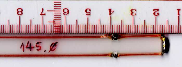
| 9. | Repeat 5 to 8 until the designed frequency is reached and lowest SWR reading
(usually when resistance is close to 50 ohm) is achieved. Solder the shorting conductor
at D, E to make it permanent. (See below photo)
| |||
Caution
Do not allow section BDEG (especially near the BG end) to touch conducting object during transmission! The antenna will not function until the conducting object is removed. The voltage at B,G is very high during transmission. With 20W of 2M transmission, the RF voltage can easily light up a small picnic use fluorescent tube held close to (not touching) this point. However, point D,E is of zero voltage. It does not matter even if you short it to ground (as a lightning protection measure).
Acknowledgments
I would like to thank Mr K. H. Lee (VR2GY) for showing me this idea of antenna construction.
References
See "Antenna" in Web page of BV3FG
Article by K4ABT