
____________________________________________
WM918
to TNC / UIDIGI INTERFACE
____________________________________________
This project was inspired by
a need to run an APRS compliant weather station in a portable
location without the need to run a PC. There are currently a
couple of WM918 standalone weather station projects about. These
are generally based on the PICE interface and while quite useable
in the form of a standalone weather station, they don't perform
any other function. The thought was that in a remote location the
flexibility of interfacing a weather station easily into an
existing UIDIGI wide digipeter or standard TNC or similar, could
be of some benefit.
This interface will read in
the serial binary data from the WM918 weather station and convert
it into a useable APRS compliant weather beacon, in the position-less
weather format.
The circuit is based more or
less directly on the PICE interface by TAPR, with the modem chip
and other associated parts removed. In fact a PICE could be used
for this project.
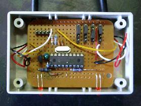
Top left hand corner of the circuit, 4 pin header, is the in circuit programming header. The various jumpers on the top right hand side of the circuit are for option selection. These are actually designated as switches with pull up resistors on the cct diagram. The bottom left LED is the data send indicator, and the bottom right led ( yellow on the cct diagram) is the valid data decode indicator.

The serial connections to both the WM918 and the TNC are directly connected to the interface. There is no need to use an extra RS232 level converter chip with this circuit. The specifications for the pic chips allow for direct interfacing to standard RS232 levels via a current limiting resistor. I have yet to find a tnc, gps, Kenwood radio etc that doesn't work with this configuration.
The following is the interconnecting required between the WM918 / PIC interface / TNC
 |
NOTE: that pin 3 of the WM918
is connected directly to pin 2 of the tnc. This is to provide a -v
~ 10v to the pin 3 of the WM918. This is needed for the RS232
driver within the WM918 to function correctly.
The Pic interface circuit derives its supply voltage from the RTS line on the com port. The circuit can be modified if people feel that this isn't the way to go'. However I've measured the current draw of the interface, with one led on and it's around 5ma. This is easily within the current drive level specification for RS232 o/p.
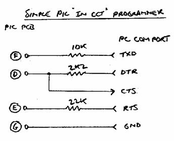
I've included the ability to do in circuit programming of the interface by means of a simple Pic programmer comprising several resistors. I've made a programming cable that contains the resistors in the DB9 back shell.
 |
|||
 |
|||
I use the program ICPROG version 1.05A which is windows based and will run on any windows platform from W95 through to XP.
It can be downloaded from http://www.ic-prog.com
The settings for this program
can be a little bit finicky but I've always managed to get it
running ok, sometimes with a bit of judicious fiddling. With the
simple resistor programmer in use, set the Hardware settings in
ICprog to JDM.
If you're running windows XP try setting windows compatibility mode to Windows 95. Seems to help with a few errors!! .
Here is the latest available version of the hex file for the pic chip. latest firmware
Want the circuits and diagrams from above? You can get them here. circuits.zip
When first powered up the yellow led should flash half a dozen or so times. This will indicate that power is being supplied correctly to the interface and the micro is running. After a several seconds the yellow led will flash intermittently. This is the interface reading in and assembling the required data. When the interface is ready to send out data, as set by the timing jumpers, the red led will flash briefly. This indicates the position-less data stream being sent out.
The terminal / RS232 port in the TNC must be set to these values via configuration dip switches etc:
The data format is 9600 bps. 8 data bits. 1 stop bit . no parity.
A target position-less
weather frame as sent:
_02160631c153s006g007t080r000p000P000b10130h56uRSW
Note the '_' designating a position-less weather packet and the last four characters represent 'u' for UIDIGI and RSW for Radio Shack Weather station or WM918 or WX200.
When setup in dumb TNC mode the 'u' is replaced by the letter 't' to signify dumb tnc mode.
Jumper Settings
SW1 - RB4 off = UIDIGI MODE on = DUMB TNC MODE
SW2 - RB3 off = zero minutes on = 5 minutes
SW4 - RA3 off = zero minutes on = 10 minutes
SW3 - RA4 off = zero minutes on = 20 minutes
SPECIAL CASE : When SW2, SW3, SW4 are all off the output data rate is in fact 1 minute not zero minutes as per table.
This is useful for testing purposes and for uidigi mode or for use with various tnc's that control their own beacon rates of their auxiliary inputs.
The data send timing is in multiples of 5 minutes, ( other than the special case of 1 minute as mentioned above). Any time interval between 5 minutes and 35 minutes can be set by the jumpers.
For example : for a data send rate of 15 minutes set SW2 = on ,SW4 = on, SW3 = off
Uidigi mode is set by SW1 = off. In this mode the weather data is sent on one line followed by a single carriage return character. This mode is suitable for UIDIGI digipeters and also TNC's that are capable of handling auxiliary input ie. the KPC3 etc.
Dumb TNC mode is set by SW1 = on. In this mode a [Control C] character is first sent, followed by a carriage return character, the 'conv' command, another carriage return character, the actual weather data string and a final carriage return character. This mode is suitable for ANY tnc, the actual weather beaconing rate being set by SW2, SW3, SW4
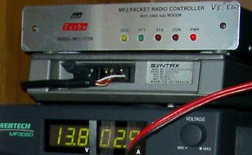
This is one of my portable uidigi setups, comprising of a MFJ1270b TNC with uidigi firmware v1.9 beta 1 and a Motorola Syntrx VHF radio.
UIDIGI MODE EXAMPLE SETUP
The following setup for UIDIGI has been tested to work satisfactorily. Settings and timings can be tweaked to suit the individual's requirements.
DIGIC VK5EX-7
DIGIP 1
UNPROTO APNU19
BT 1 !0000.00SR00000.00E_UIDIGI
1.8 BETA 6 (RELAY,WX)
BT 2 >UIDIGI 1.9, WM918
WX STATION standalone on test
BE 1 1200
BE 2 1200
B 1 WIDE3-3
B 2 WIDE3-3
BEACONO 1 60
BEACONO 2 60
AUXD APNUxx
AUXP WIDE3-3
AUXR 1200
UIT _
UIF _
UIS 0
UID RELAY
DUMB TNC MODE EXAMPLE SETUP
The following setting have been successfully tested on a MFJ1270b but should also work fine on any TNC capable of entering standard converse mode with the 'conv' command. Final parameter settings can of course be fine tuned to suit individuals requirements.
MYCALL VK5EX-7
MYALIAS RELAY ( whether this is set depends on local requirements )
UNPROTO APRS v WIDE,WIDE2-2
BEACON TEXT
!0000.00SR00000.00E_TNC MODE & WM918 (RELAY,WX)
BEACON EVERY 120 ( note that this controls the beacon text only, not the WX rate)
For any further information regarding this project Email [email protected]
Good Luck ! and 73 from
Andrew McDade .. VK5EX ..