 |
An Inherent Dropout with Certain Capacitive Loads and how to Fix the Problem |
|
|
An Inherent Dropout with Certain Capacitive Loads and how to Fix the Problem |
Introduction
We draw the attention of Z match users to a drop-out region in the load range of that tuner which was not noticed in earlier tests. We explain the reason there is such a region and discuss some ideas on how to deal with the problem.
In leading up to the drop-out region, we have introduced some theory to explain how the Z Match is able to work into a range of load conditions and in particular, load resistances lower than might be expected.
Discussion is centered around the Single Coil Z Match but the theory also applies to the Two Coil Z Match and in some circumstances, the drop out region can also apply. This is discussed further in the text. For more detail of the Single Coil Z Match on this Internet site, Click Here.
Background Theory
The Z match tuner can be resolved as a simple L network of series capacity and shunt inductance combined with an output coupling circuit. For fundamental reasons, an L network of this type cannot match a resistance component loaded in parallel across its output that is lower in value than the desired reflected load (usually 50 ohms). In practice, this lowest value is even further increased because of limits in the adjustable range of the series capacitor. However, if the load resistance is applied to the output via a series reactance, the load resistance (now the series resistance component) is reflected across the L network output as a higher parallel value. Provided there is some series reactance, the L network can therefore match values of series resistance in the load lower than the nominal minimum value. The Z match output circuit makes use of this property.
To further illustrate the effect in the Z match, refer to the circuit figure 1 (a) and its equivalent 1 (b). The impedance components Ra and Xa, reflected via the coil from the antenna, are shown in series with an inductive component XLc, reflected from the under-coupled coil itself. The series circuit can be considered as a parallel equivalent with parallel components Ra' and Xa'. Provided (XLc + Xa) is a finite value, then the equivalent shunt resistance Ra' is higher than Ra and the higher the series reactance then the higher Ra' becomes. For resistive loads, the undercoupled output coil reflects series reactance component XLc on its own. When there is inductive reactance coupled in from the antenna, Ra' is further increased and the ability of the L network to match low resistance loads is further enhanced.
 |
Figure 1 - Reflected components across L match. XLc = Inductive reactance reflected from under-coupled coil Xa = Series reactance reflected from antenna via coil. Ra = Series resistance reflected from antenna via coil. Xa' & Ra' are the equivalent parallel components. If (XLc + Xa) is finite, then Ra' is greater than Ra. If (XLc + Xa) = 0, then Ra' = Ra and Xa' is infinite. |
Before proceeding further into the main point of our discussion, we will clarify what happens to shunt component Xa' connected across our L match network. First look at Figure 2. In 2 (a), we have our Z match coil primary winding with a tuning capacitor connected across it. Combining these two elements we have a single reactance 2 (b) which can be set over quite a wide range by adjusting the tuning capacitor. Let's split this into two imaginary reactances in parallel which we will call XLm and Xp (refer 2 (c)).
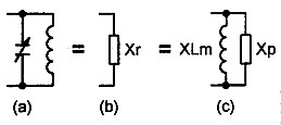 |
Figure 2 - Shunt tuning equivalent. (a) Tuning capacitor and primary coil in parallel = (b) Resultant shunt reactance (one component) = (c) Xr split into two components (refer Fig 3). |
Now to Figure 3, which depicts the L match loaded with the equivalent parallel components previously discussed. Series component XCm (our series tuning capacitor in the Z match) and shunt component XLm are the values necessary in the L match circuit to match reflected shunt resistance Ra'. Component Xp is equal in value but opposite in sign to reflected shunt reactance Xa' and so Xa' is cancelled out.
 |
Figure 3 - L Match with parallel equivalent load. XCm = Series capacitive reactance of L match. XLm = Shunt inductive reactance of L match. Xa' = - Xp. Note: XCm and XLm have values necessary to transform Ra' to a resistance of 50 ohms as seen at the network input. |
Having eliminated Xp and Xa', we now have the diagram Figure 4 (a) with parallel components XLm and Ra' in series with XCm. Making another conversion of the parallel components to series form, as shown in 4 (b), we get inductive reactance XLm' and resistance Ra" both now in series with XCm. We now see a series resonant circuit. The series reactance XCm is equal but opposite in sign to reactance XLm' leaving just resistive component Ra" (Figure 4 (c)) which is 50 ohms and the correct load for our transmitter.
 |
series form. Ra' = Parallel resistive load of L match section (greater than 50 ohms) XLm = Shunt Inductive reactance of L match (to make Ra" = 50 ohms) Ra" = Equivalent series resistance (equal to 50 ohms) XLm' = Equivalent series inductance XCm = Series capacitive reactance of L match XCm = - XLm' |
The Problem
Our problem area occurs for certain capacitive loads. Referring again to Figure 1, if the reflected reactance Xa is capacitive and it is small compared with the inductive reactance XLc reflected by the coil, or if it is much larger, then there is unlikely to be a problem. However, if this capacitive reactance is of such a value as to cancel or near cancel the inductive reactance, then the property which causes the circuit to reflect the series resistance component as a higher parallel value is nullified or reduced. Hence, for a given frequency, there is a range in the value of capacitive reactance referred to the Z match input for which very low load resistance values in series cannot be matched.
The existence of this characteristic was fairly recently observed by Graham VK3IY when he did some theoretical analysis on the operation of the coil. Subsequent tests carried out on an AR Single Coil Z Match by Lloyd VK5BR clearly confirmed his observation.
Tests on the sample AR Single coil Z Match unit revealed a critical capacitive reactance range when combined with resistance below a critical resistance value. The range in values (including those in the unit modified to switch in 1.8 MHz) are shown in Table 1. The resistance given is the minimum value when the capacitive reactance is in the middle of the range shown and can be considered as the worst case value. For 3.5 to 28 MHz, the values apply to a maximum tunable series capacitance in the Z match network of 350 pF. For 1.8 MHz, the value applies to a maximum tunable series capacitance of 1000 pF
| Frequency Band MHz | Xc (ohms) | Ra (ohms) |
| 16 to 32 | below 16 | |
| 25 to 50 | below 30 | |
| 55 to 100 | below 80 | |
| 80 to 180 | below 80 | |
| 170 to 300 | below 80 | |
| 250 to 500 | below 75 |
Hopefully, most AR Single Coil Z Match users will not have an antenna which reflects a low resistance combined with a capacitive reactance within this critical range. However, we do know of one G5RV antenna which measured an impedance on 7 MHz of 40 - j100 ohms, right in the "no-go" region of the AR Single Coil Z Match and, hence, there was a matching difficulty using that unit. Perhaps not all G5RV installations will reflect a similar load impedance on 7 MHz but it is worth keeping in mind if one has a G5RV. Also, if a different Z match with different secondary inductance is used then the critical range of capacitance will be different and might not coincide with the antenna capacitance.
How to Fix it
Faced with the problem discussed, it can be dealt with by simply shifting the load reactance along a bit so that the no-go region is out of the antenna load range being used. There are several ways in which this can be done.
(1) A capacitor can be placed in series with the antenna load, selected so that its capacitive reactance roughly doubles the reactance in the load circuit. The disadvantage with this method is that a different value of capacitor must be switched in for each frequency band.
(2) An inductor can be switched in series with the antenna load and, if suitably selected, the single inductor can be used on all bands (refer figure 5). An experimental air wound inductor of around 1.2 μH has been constructed. This consisted of nine turns of 14 B&S enamel wire wound at a diameter of 24 mm and spaced to a length of 27 mm. This worked extremely well, shifting the no-go region out of the nominated critical range on all bands.
(3) The coil secondary winding can be switched to reduce the number of secondary turns and, hence, alter the secondary inductance (refer figure 6). The secondary of the AR Single Coil Z Match has four turns and switching in a tap at three turns reduces the secondary inductance to a little over half the previous value, which is just enough to move the no-go region sufficiently on all bands except 1. 8 MHz.
 |
 |
|
Figure 5 - Modification to allow shifting of load reactance to avoid no-go region Series inductor method. |
Figure 6 - Modification to allow shifting of load reactance to avoid no-go region Secondary coil tap method. |
Which method do we use? Well, the series inductor gives the more positive no-go region shift and you only need one inductor for all bands. However, the coil tap idea saves making the inductor - so take your pick!
Whilst our discussion has tended to be written around the single coil Z match, the same no-go region can be experienced in both outputs of the two coil Z match. In the latter unit we have two coils of different secondary inductance and, for certain frequency and load conditions, it is possible to get a match using either coil output. As the coils are different, reflected reactances into the primaries are different and if this overlap occurs in the low resistance region, the no-go region can be dodged by changing from one coil output to the other.
On the Compact Coil or Rononymous Two Coil Z Match, recent tests have showed that this overlap matching condition can be achieved on the 7 MHz and 14 MHz bands. In the initial design, low resistance loads can only be matched on the 3.5 MHz band using output from coil B and hence at 3.5 MHz, this dodge is not available. However, in an article in September 1995 issue of Amateur Radio, we pointed out that if the secondary of coil A was reduced from its seven turns to four turns, then low resistance loads at 3.5 MHz could be operated using coil A output with subsequent improvement in efficiency. By adding this modification, the overlap condition for low resistance loads is also extended to 3.5 MHz and the dodge becomes available on this band.
At 21 MHz and 28 MHz, matching of low resistance loads is only available using coil B and, hence, other correction methods, such as switching in the series inductor, might need to be applied. The secondary inductances in the two coil unit are higher than in the single coil unit but a satisfactory shift in the no-go region was still achieved using the previously described 1.2 μH series inductor.
If the two coil Z match is only used on the lower HF bands then perhaps the only modification necessary is to reduce the number of secondary turns for coil A as discussed. An RSGB model version of the two coil Z match has not been available for no-go region experimentation but similar results to those obtained using the compact coil version are anticipated.
Conclusion
The Z match is well known for its ability to match a wide range of load impedance conditions over the HF spectrum. However, we have described one particular load condition which, if experienced, might require some extra attention.
Our discussion has concentrated on the AR Single Coil Z Match and Compact Coil or Rononymous Two Coil Z Match, both of which have received prominence in past issues of Amateur Radio. In the single coil Z match, we have described how this no-go load condition can be avoided by switching in an additional component or switching an output coil tap. For the two coil Z match, we have discussed how the need for these further components is avoided in the 3.5 to 14 MHz range.
Quite apart from the discussion on the drop-out region, the section headed "Background Theory" gives an insight into just how the Z Match arrangement works.
A Final few words from the authors
From Graham VK3IY:
One can follow the evolution of the Z match, with the wisdom of hindsight. The early experimenters must have noticed that it did not always work. They may not have understood the reason why, but used a dual system so that one or the other would certainly work. This became standard practice (50 yrs?) until Lloyd came along with his single coil design. Following what little analytical help I was able to provide, he came up with the elegant solution of a simple switch. There is now no point whatever in building a two coil Z match.
From Lloyd VK5BR:
The Single Coil concept was first introduced to amateur radio by Tom Seed (ZL3QQ) in Break-In. What I did was was to experiment with the design and make changes so that it would match a wide range of load conditions on all the HF bands. I also developed circuitry to extend operation to 1.8 MHz. The Drop-Out regions on loads of low resistance, combined with capacitance, are very narrow and in my initial tests I missed identifying them. Graham first observed the regions when he did a more analytical study of the circuit. Had he not done so and convinced me that there were sound theoretical reasons why they must be there, this matching limitation in the Single Coil unit might never have been understood and fixed. Graham gives me credit for introducing the simple idea to fix the problem but he also must take credit for identifying the problem in the first place. I think his last sentence is a significant one: "There is now no point whatever in building a two coil Z match".
References
1. Random Radiators (VK3AFW & VK3OM) Rononymous Z Match, Amateur Radio March 1990.
2. Lloyd Butler VK5BR - Tests on the Compact Coil Z Match, Amateur Radio, December 1990.
3. Random Radiators (VK3AFW & VK3OM) - AR Single Coil Z Match Amateur Radio, February 1993.
4. Lloyd Butler VK5BR - AR Single Coil Z Match - Amateur Radio, April & May 1993.
5. Lloyd Butler VK5BR - Efficiency of the Z Match - Amateur Radio, September 1995 .
6. Graham Thornton VK3IY - An L of a Network - Amateur Radio March, April & May 1995.
7. Graham Thornton VK3IY Technical Correspondence - The choice of ATUs: L, Z, or T Amateur Radio August 1995.
8. Lloyd Butler VK5BR - The Single Core Z Match Simplified