
The basic Single Coil Z Match discussed in the previous article was never meant for operation at 1.8MHz. However, it can be made to work on that band by adding capacity to the two tuning components. Tests have shown that to operate at this frequency with load resistances as low as 10 ohms, capacitors as large as 1100 pf are required for the input series circuit and as large as 950 pf shunted across the the primary coil. Curves illustrating this were included in my article publihed in Amateur Radio, May 1993. As far as shunt capacitance is concerned, this is only added to the value across the full coil and nothing is added at the coil centre. The curves were plotted for the complete load range of 10 to 2000 ohms although for most of us, with electrically short antennas on this band, resistance above 50 ohms is probably irrelevant.
Figure 1 shows the original Z Match circuit modified to include 1.8 MHz. The addition of three fixed capacitors and a 4 position switch gives the whole load resistance range at 1.8MHz. If satisfied with just the lower resistance range, two fixed capacitors and a two position switch would do the job. To check operation, I used ordinary 350 volt mica capacitors. With these fitted, I fed over 200 watts through the tuner into a dummy load and later into my 1.8MHz antenna. Nothing arced or blew apart but I strongly suggest higher voltage capacitors if they can be obtained. I later built a unit with higher voltage fixed capacitors and wider spaced variable capacitors for higher power operation.
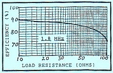
Figure 2 shows the results of power efficiency tests at 1.8 MHz. Efficiency is around 85 to 90% for load resistances of 50 ohms and below. As load resistance is raised, efficiency falls away, but as indicated in the earlier paragraph, this is probably irrelevant for most amateur antenna installations used at 1.8 Mhz..