Introduction
If the radio amateur builds or services his own gear, he needs, if nothing else, some means to measure the basic units of resistance, capacitance and inductance. Most amateurs would have a multimeter which can measure resistance. Some digital multimeters include capacitance measurement. Bridges which measure both resistance and capacitance are quite common items in the radio shack but not many radio amateurs have the means to measure inductance.
If one has access to a Q meter, an unknown RF inductor can be resonated with the tuning capacitor on the Q meter. The inductance is then calculated from the frequency used and capacitance indicated on the tuning capacitor scale. This is a method I have used in the past but I felt I needed something which could give me a direct reading of inductance to eliminate the calculation and speed up the process.
For my own experimental use, I keep a range of miniature inductors (or chokes, as shown in the catalogues). These are made by a number of different manufacturers and are normally available from electronics stores in preferred values starting at 1 microhenry and sometimes going as high as 10 millihenries. Some look like small resistors and some like small capacitors. Some are colour coded and some are marked in inductance value. They generally have quite high Q and measure quite close to their nominated value. I find these inductors very useful for application in filters and tuned circuits which use two pole inductors (i.e. no taps or secondary winding). Sometimes I find I am confused in reading the coded or marked value and need some means to check it out.
The inductance of air wound coils can be calculated by using established methods such as Wheeler's formula. The inductance of coils with ferro-magnetic cores can also be estimated using the Al factor data supplied by makers of the core material. However, a means to measure the inductance is useful to check if one is in the right ball game.
These are the reasons which led me to build the inductance meter described in this article. This instrument measures inductances from 0.1 microhenry to 3 millihenries divided into four ranges set by a switch. It operates from 12 volts, and is powered by eight AA type cells attached to the unit.
Background
I initially referred to Drew Diamond's unit in Amateur Radio, November 1992 to see if it fitted my needs. Drew used a fixed crystal oscillator at around 3.5 MHz to source a bridge where he compared the unknown inductor against a known 5 uH inductor. The bridge was balanced by adjusting a potentiometer which had its scale calibrated in terms of inductance. The meter measured a range of 0.5 to 20 uH.
I needed a wider inductance range than this. Also, I was a bit concerned that no provision had been made in Drew's circuit to balance out the resistance components of the reference and unknown inductors. If the two resistance components were largely different, and particularly if one of them (the unknown) was fairly low in Q, the dip shown in the balance meter would occur with the potentiometer reading offset from the calibration. I guess I could have modified the bridge to include resistance balance but I decided to operate my circuit in a different way.
I have used a fixed frequency source as in Drew's circuit but extended this to four frequencies to expand the inductance range. Instead of using the bridge, the unknown inductor is resonated by adjusting a variable capacitor in parallel with the inductor. The parallel tuned circuit is energised from the oscillator source via a meter which monitors the current into the circuit. The system is illustrated in Fig 1. Resonance is indicated by a dip in current as shown on the meter. A dial attached to the variable capacitor is calibrated in terms of inductance.

Circuit Detail
Influenced by Drew's crystal controlled, Colpitts type oscillator circuit, I wired up the circuit and proceeded to search through my box of crystals for precise frequencies which would give me the frequency spread I needed.
This proved to be a bit difficult as I needed to space the frequencies carefully so that each inductance range just overlapped the adjacent one. I finally decided that crystal controlled stability was not needed and substituted selected inductors from my store of miniature chokes. I settled on four frequencies of 16 MHz, 5.2 MHz, 1.32 MHz and 350 kHz for four ranges labelled A, B, C and D.

The complete circuit of the inductance meter, which includes the oscillator (V1), is shown in Fig 2. The oscillator inductors LI to L4, switched by S1a, are 1 uH, 12 uH, 180 uH and 680 uH. With capacitors C4 and C5 fixed, I found difficulty in making the circuit work over the whole frequency range without some other component change apart from the inductors. Switch S1b, ganged with S1a, connects in C2 and C3 on the lowest frequency. R3 or R4 are paralleled with R5 to increase emitter current on the higher frequencies.
In retrospect, if I decided to build the unit again, I think I would prefer to use the lambda negative resistance circuit which I recently described in a dip meter. The lambda circuit did not require the extra switching and its waveform was much better.
The transistor used for V1 is a type 2N3563 but any other small signal NPN transistor with a high frequency cut-off would do the job.
The inductance measuring circuit is isolated from the oscillator by emitter follower stage V2. The tuning capacitor C9, in the measuring circuit, is a two gang 450 pF miniature variable with both sections paralleled to provide a capacitance range of around 40 to 900pf.
The current into the measuring tuned circuit is monitored by a 50 micro-amp meter connected via an associated rectifier circuit. RF drive is set by potentiometer RVI. This must be adjusted when making a measurement as the off-resonant current varies quite a bit, particularly in changing from one range to the other.
The test procedure is as follows: First set the drive to minimum. Connect the unknown inductor. Advance the drive to near full scale deflection. Adjust the capacitor for a dip and read off the inductance. Return the drive to minimum in case the meter goes beyond full scale next time it is used for a measurement.
Using the frequencies and variable capacitor nominated, the inductance range is as follows: Range A, 0.1 to 1.5 microhenries; Range B, 0.9 to 20 microhenries; Range C, 18 to 250 microhenries; and Range D, 240 to 3000 microhenries.
Powering
To make the unit more portable, it is powered from a dry battery. The oscillator was not stable at a supply voltage below 8 V and operation could be marginal from a 9 V battery when it is partly discharged. Because of this I decided to use a 12 V battery and stabilise the voltage at 10V.
The 10V is set by two 5.1V 400 mW zeners (ZD1 and ZD2) connected in series, only because I didn't have a 10V zener on hand. The LED with the 9V zener (ZD3) in series is a little circuit to indicate when the battery needs replacing. Normally the LED glows dimly but, if the rail voltage falls much below 10V, the LED extinguishes. The type of LED shown has an internal series resistor. This is a type I had available but an external resistor of at least 1000 ohms would be needed for the usual LED to limit current through the diode.
Assembly
Most of the components used, including the aluminium box, the 50 uA Calibration meter and the variable capacitor, were recycled from dismantled gear. The meter, mounted in a deep tubular housing and calibrated with a temperature scale, must have been originally recovered from an aircraft instrument panel. The calibration in temperature was of no concern as the meter is only used to indicate the tuned circuit current dip.
Inductors L1 -L4 and components C2, C3, R3 and R4 were mounted around rotary switch S1. The rest of the minor components were mounted on several single-row tag strips at convenient places inside the box.
For the critical capacitors in the oscillator circuit (Cl to C5), silver mica was used (I have little faith in ceramic capacitors for such applications). There were no special precautions taken with the wiring and some leads were a little longer than they ought have been. However, I experienced no problems because of this and it all worked fine once I had won my battle with the oscillator. Minimising lead length between the variable capacitor and the test terminals is important as these add inductance in series with the test sample. This is corrected for in the calibration but it could be a problem in measuring small inductors if the leads are too large.
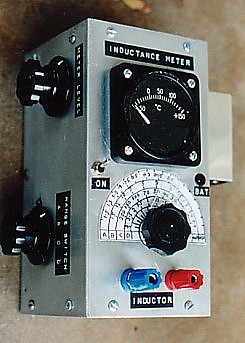
The layout of meter and controls is shown in the photograph. As the case was recycled it was not quite made to order. With the meter and calibrated scale on the top, there was insufficient room for the drive control and the range switch and these were mounted on the side. Also, whilst the inside was by no means cramped, there wasn't quite room to mount the 12 V battery holder internally and this was fitted externally on the side opposite to the drive and range switch.
The dial calibration scale was drawn up on paper in four sections without calibration points and the scale was glued to the box.. Calibration points were added later. A cursor was made from perspex sheet and glued to a knob mounted on the variable capacitor shaft.
Calibration
Without access to another accurate instrument calibrated for small values of inductance, a little bit of ingenuity was needed to calibrate the unit. In my case, I was able to make use of my own range of miniature chokes. Obviously these are made to a tolerance but, by using a number of samples, including different samples from different brands and using various combinations in series and parallel, I averaged out readings to obtain each calibration point marked on the scale.
Had the range of reference inductors not been available, I might have used the following method: Firstly a reference unit scale (say 0 to 100) is provided as a further scale section. Disconnect the variable capacitor from its circuit and, using a digital capacitance meter or a capacitance bridge, measure the capacitance at a number of points over its adjustable range. Record these capacitance values against the dial calibration points. For one of the four oscillator frequencies, calculate the inductance required for resonance at each capacitance value using the normal resonance formula. Using graph paper, inductance can now be plotted against calibration units by joining up the reference points derived. Repeat the exercise for the other three frequencies resulting in a set of calibration curves to mark off the scale at will. Alternatively (but not so convenient), one might choose to only have the unit scale on the instrument and always refer to the calibration curves when taking a measurement.
Using this second method, a correction factor would need to be made on the lowest inductance scale because of inductance in the leads between the capacitor and the test terminals. For example, a lead length of 10cm would add in around 0.1uH. For the lowest scale, it would be wise to make up several small air-wound inductors, calculate their inductance using Wheeler's formula and use them as a reference for correction.
Some Final Thoughts
The article describes a simple circuit which can check out inductors in the range of 0.1uH to 3mH. In fact, the main circuit complication is the provision of an oscillator which can work on four widely different frequencies. A Colpitts type oscillator has been used in the unit described but any other form of oscillator could be made to do the job. The actual frequencies are not too important, except that they need to be spaced so that the inductance ranges are complementary and slightly overlap each other to ensure a defined dip. The frequency spacing might also be dependent on what variable capacitor can be obtained and what tunable capacitance range it can provide.
Concerning the oscillator as built, suitable frequencies were achievable using four fixed off-the-shelf inductors to set tuning for the oscillator. However, because of variations in tolerance of these components and associated capacitors, a repeat of the circuit might involve some trimming of the inductor values. One might also choose to wind up the coils, perhaps with provision of a tuning slug so that precise frequencies could be set.
Some ingenuity is needed to calibrate the unit and I have discussed ways of how this can be done. Having completed this, the unit becomes a very useful instrument to have at the test bench.