
INTRODUCTION
The use of interference signal cancellation has been around for some time. The idea is to use an auxiliary antenna (almost any random length of wire) in addition to the main receiving antenna. As the two antennas are physically spaced from each other and also unlikely to have similar field patterns, the amplitude and phase difference between the two antennas for an interfering signal can be expected to be different to that for the desired signal. This particularly applies to a localised interference source where that source is largely coupled into the antenna by induction. This induction field follows a different law of signal attenuation verses distance to that of the radiation field by which the distant desired signal is being received. The two antenna outputs are combined after modifying their relative signal levels and phase such that the interference signal from one antenna is equal but opposite in phase to that from the other antenna. The interference signal is cancelled but as the two desired signals have a different amplitude and phase relationship, a resultant desired signal component is retained. Of course for all this to work. the interference waveform must be continuous and reasonably stable in its shape and amplitude. From my own experience. the system works extremely well for power line noise and frequency dependent noise bars generated by TV line time base and computers.
To achieve this form of interference cancellation, some device is required which can adjust the amplitude and phase of one or both of the antenna signals. Relative phase between the two signals must be adjustable over a 360 degree range to cope with different signal conditions. In 1976, Drew Diamond VK3XU submitted articles on a passive method of mixing and adjusting the two antenna signals. To provide 180 degrees phase shift, Drew provided a reversing switch in the main antenna circuit. A matching network consisting of a tapped inductor and two variable capacitors was connected to the auxiliary antenna. Further adjustment of phase was achieved by detuning the matching network. Amplitude was adjusted by a potentiometer in each antenna circuit. The idea of a passive unit, as Drew had used, seemed attractive in that there were no transistors to encourage cross modulation and of course no power required apart from relay control. On the other hand, I questioned whether detuning an antenna matching network was adequate to give the complete range of phase shift which might be required.
Phil Williams VK5NN drew our attention to a unit called a QRM Eliminator distributed by a British company SEM. Phil owns one of these units and has reported very favourably on its ability to balance out unwanted signal. The SEM unit is an active device powered from 12VDC and is provided with phase and amplitude adjustment controls. Their Mark 1 unit is switchable between amateur HF bands but a later Mark 2 unit has broadband inputs with no front end tuning and continuous coverage without switching. Phase shift control is achieved with resistance-capacity networks for phase shift control..
With all this background, I decided that I should attempt a circuit design of my own. At that time I had no idea what form of phase control circuitry SEM might have used and I first built the noise cancel unit using my own arrangement of resistance-capacity phase shift networks ( reference 1). I tuned the front input rather than use a broadband circuit which I feared could suffer from interference due to cross modulation from out of band strong signals.
I thought my first design was a bit complicated and I eventually came up with a different idea to achieve the phase shift in a new cancelling unit which is described in this article.
In principle, phase adjustment is very simple. If a signal is loosely coupled into a parallel tuned circuit, the phase produced across the tuned circuit can be easily shifted over a 90 degrees range as the circuit is tuned, from part way down one side of the resonance curve, through resonance, to part way down the other side. The effect can easily be demonstrated by loosely coupling a signal generator into a tuned circuit and simultaneously monitoring, with a dual trace CRO, the signal generator output and the signal across the tuned circuit. The precise amount of phase shift for a given frequency offset can be derived from the curves (figure 1) reproduced from Terman.
To achieve 180 degrees of phase shift, we use two identical tuned circuits with their tuning capacitors ganged together. The two tuned circuits must be loosely coupled or separated by an amplifier isolating stage. The 90 degrees shift in the second circuit is additive to that in the first circuit giving us a 180 degrees of range. Of course the amplitude also varies across the resonance curve. In practice, this is no problem as the phase and amplitude controls have to be progressively adjusted, in turn a number of times, until the interference null is achieved.
For the circuit detail, refer to figure 2. In this diagram, L1-C1A and L2-C1B are the two tuned circuits coupled by resistor R2. Inductors L1 and L2 are identical and capacitors C1A and C1B are a ganged variable pair. In practice, tracking of tuning does not appear to be critical and hence there is no need to be too concerned about precision matching of the inductors. The circuit, as shown, runs with a fairly low Q and almost any identical pair of inductors can be used provided they are selected with the right inductance for the frequency concerned. Matched aerial and RF coils from an old valve receiver can be put to good use here. In this case, the primary winding of the aerial coil can be used to couple the auxiliary antenna instead of using coupling resistor R1.
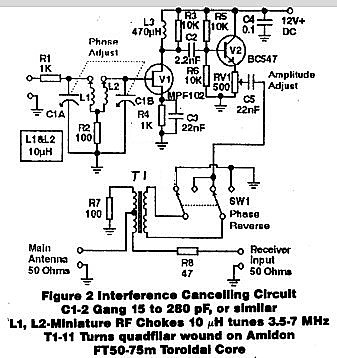
Inductors specified in figure 2 (and figure 3) are miniature RF chokes which can be purchased from electronic stores for about one dollar each. These are very convenient because they are no larger than a resistor or small capacitor, can be supplied in precise values of inductance and save the effort of having to wind the coils. The inductance value (10 uH) shown in figure 2 allows tuning between the 3.5 and 7 MHz bands. The resonant tuning range is greater than this but a tuning overlap must be allowed for phase adjustment either side of resonance at the extreme ends of 3.5 and 7 MHz. For 1.8 to 3.5 MHz we can use 39uH, for 7 to 14MHz - 2.7uH and for 14 to 28MHz - 0.68uH. If complete HF band coverage is required, a 4 pole 2 position switch can be used as shown in figure 3.

INTERFACE & MIXING
Two transistor stages follow the phase shift tuning system. FET stage V1 provides high input resistance to prevent loading of the tuned circuits and provides voltage gain which is needed in reserve in the system. Emitter follower stage V2 provides a low source resistance to drive the receiver input via the mixing circuit. Potentiometer RV1 is used to set amplitude in adjusting for interference null. The potentiometer must be a non inductive type (not wire wound) with a preferred tapered resistance characteristic to improve adjustment resolution when set near minimum. If a tapered pot is not available and difficulty is experienced in adjusting near minimum setting, the gain of the amplifier can be reduced by reducing the value of resistor R3 or providing a switch to connect in a lower value. The final component in the phase control chain is switch SW1. This reverses the phase of the auxiliary signal to extend the 180 degrees of phase adjustment to 360 degrees.
The signal from the auxiliary circuit is combined with that from the main antenna via transformer T2 which, with its associated circuitry, prevents interaction between the two signal sources. Readers with a Telecom background might recognise T2 circuit as similar to the Hybrid Coil circuit used to achieve two way amplification on single pair telephone trunk lines.
For the isolation to work, the receiver is assumed to present a 50 ohm resistive load. Added to this is series resistor R8 (nominally 50 ohms) making a total of 100 ohms which is balanced against 100 ohms resistor R7. The main antenna is loaded by these two 100 ohm circuits in parallel, hence 50 ohms load is presented to the main antenna. As the lower two windings of T2 are in antiphase, the inductance of T1 in series with the main antenna is cancelled out. Furthermore, no signal from the main antenna can be induced into the upper winding of T1 which is connected to the auxiliary output.
As far as the auxiliary circuit is concerned, its signal is induced into the lower two windings of T1 which are connected across the two 100 ohm circuits in series, that is, 200 ohms. As there is a 1:1 turns ratio, 200 ohms is reflected back to the auxiliary output circuit. Whilst half the auxiliary output power is fed to the receiver input, the auxiliary output voltage to earth is virtually zero at T2 centre tap. As this is the main-antenna connection, auxiliary output signal is prevented from reaching the main antenna. Of course, the usual 50 ohms input to the receiver is a nominal value and the degree of isolation between the two circuits depends on how near the receiver input circuit is to a resistance of that value.
TRANSMIT-RECEIVE FACILITY
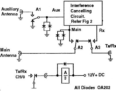
For the DX listener, figure 2 in conjunction with figure 3 makes up a complete system. However for amateur radio use, extra circuitry is required to switch out and provide protection for the interference cancelling unit when transmitting. Relay A is operated on transmit by normal contacts of the TX/RX relay in the transceiver. On transmit, relay contacts A2 and A3 switch out the balancing and mixing transformer and connect the transceiver direct to the main antenna. Relay contacts A1 disconnect the auxiliary antenna and earth the auxiliary input. Diodes across the interference cancelling input and output circuits provide additional surge protection.
OPERATION
To balance out an unwanted signal or noise, first advance the amplitude control to a suitable level and set the phase control for maximum signal or noise (i.e. circuits L1-C1a and L2-C1b are near resonance). Then set for a balance by adjusting the phase and amplitude controls for lowest noise or interference, one after the other a number of times, until an interference null is achieved. If a null is not found, or the null is not very definite, the phase is reversed with the reversing switch and the procedure repeated.
In my first unit, a tuned input from the auxiliary antenna was found to be necessary to prevent cross modulation from local broadcast stations and other signals which caused 'birdies'. In the new unit, the input tuning system combines this function with phase control. Whilst the tuning might be set a little off resonance, it still provides rejection of out of band signals.
A LATER CHANGE
The load resistance placed on T1 by the receiver is built out to 100 ohms by resistor R8. This attenuates the signal to the receiver a little when the cancelling unit is switched in. In my own unit, I decided to eliminate this and I later replaced R8 with a matching transformer T2 as shown in figure 5. I then experienced some instability in stage V2. (Sometimes emitter follower stages tend to become unstable if fed directly into a reactive load). To tame this, a new R8 (47 ohms) was connected in series with C5.
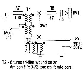
Please note that R4 in figure 2 is 1 kohm. This was wrongly marked as 100 kohm when originally published in January 1993 Amateur Radio.
SUMMARY
A interference cancelling system is described, using resonant circuit detuning in the auxiliary antenna circuit for phase adjustment. In preference to a broadband input circuit, the tuning up front in the auxiliary antenna circuit also provides a degree of rejection to out of band strong signals which might otherwise cross modulate the auxiliary signal. Furthermore there are no active components in the main antenna signal path which might encourage cross modulation.
If you have a local interference problem and are interested in a noise cancelling system, I suggest you give this circuit a try.
REFERENCES TO MY ARTICLES IN AMATEUR RADIO
1. September 1992 - An Inteference Cancelling System for your Receiver or Transceiver
2. January 1993 - More on Interference Cancelling and a New Circuit
3. January 1994 - Some Further Notes on Interference Cancelling