
|
|
|
Introduction
In home-brewing a single sideband (SSB) transmitter, an essential requirement is a suitable intermediate frequency filter. Such a filter must have sufficient bandwidth to pass one sideband whilst having response shaped to attenuate the other. The ladder filter, using a number of crystal elements of the same frequency, has been popular in home-brew equipment as a means of achieving the required response.
Several articles in recent issues of Amateur Radio have dealt with these filters. Harold Hepburn (VK3AFQ) made use of such a filter in his building blocks and discussed their performance in the August 1987 issue. Rob Gurr (VK5RG) is well known in our region for his experimentation with home-brew circuits. In the November 1982 and January 1984 issues of the journal, Rob described experiments he had carried out on these filters.
Both Harold and Rob have referred to articles prepared by J A Hardcastle (G2JIR). The most useful of these is one published in the February 1979 issue of Radio Communication. In this article, a method is described by which the precise components can be selected for a given set of crystals to give a required bandwidth. The method initially entails setting up a test circuit with two of the crystals to measure a sample bandwidth.
Using this measurement as a reference, the circuit component values are then calculated to give the required bandwidth in the complete ladder filter. Coefficients are given which enable calculation of component values for filters containing three, four, six, or eight crystal elements.
The G3JIR article covers quite a bit of ground, but for those who might be interested I thought I would set out the G3JIR procedure in a simplified form and then follow up with some results of its application using sample batches of crystals. All in all, the procedure works very well, but to carry it out, test equipment is needed to plot spectral response so that bandwidth can be resolved. Access to a spectrum analyser or some form of sweep generator makes measurement simple but such devices are not usually available to the radio amateur. The minimum requirement is a stable signal generator and a frequency counter to set accurately closely spaced spot frequencies. Some form of device which can measure signal amplitude at the frequencies concerned, such as a calibrated CRO or a VTVM is also needed.
The G3JIR Procedure
The first operation is to connect up the test circuit with two of the crystals as shown in figure 1. Capacitors (Cl) are set to an arbitrary value, suggested as 33 pF. The source resistance and load resistance are set to a value R which is calculated as follows:
R= 0.613 x 10⁶/2πfC1-------------------------------------(1)
where f = the crystal frequency in MHz
Cl - capacitance in pF
 |
The source resistance is made up of the output resistance of the sweep generator, or the signal generator and an additional resistance to make up the total value of R. The output is terminated in a resistance, also equal to R, across which is connected the input of the spectrum analyser, CRO or VTVM, via a high impedance probe. (The high impedance probe is needed to prevent detuning of he circuit.)
A spectral response curve is plotted and the 3 dB bandwidth (or bandwidth of signal within 0.707 of the level at centre frequency) is scaled off.
Filter bandwidth is approximately inversely proportional to the square root of coupling capacitance and from this relationship, a new value of capacitance (C2) is calculated for the required band width (say 2.5 kHz) as follows:
C2 = Cl (BW1/BW2)2 ---------------------------------------------- (2)
where BW1 = Bandwidth previously measured
BW2 = The new bandwidth required
A new value of R is then calculated as follows:
R = 0.613 x 10⁶/2πfC2 ------------------------------------------- (3)
 |
Capacitor coefficients for 3, 4, 6, & 8 crystal assemblies. |
Refer now to figure 2 and select the form of filter suited to the number of crystal elements it is proposed to use. (The higher the number, the sharper the filter but selection might depend on how many crystals one happens to have.) Apply the following formula to each capacitor element in the circuit selected:
C(pF) = K x 106/2πfR---------------------------------------------------------- (4)
where K= The capacitor coefficient shown in the circuit (fig 2)
f = Frequency in MHz
R = Source & load resistance derived in (3)
Wire up the filter using the capacitance values calculated. It might be necessary to parallel some preferred values of capacitors to obtain values close to those calculated.
The test circuit is again connected up but with the completely wired-up filter and with the new value of source resistance and load resistance (R) calculated from (3). The response curve is now checked and hopefully it should have the bandwidth required, with nice steep sides and high out of band attenuation.
Choice of Crystals
The choice of crystal frequency is largely dependent on what crystals one can get at the fight price. Frequencies within the range of 8 to 10 MHz seem to be the popular choice for amateur radio SSB use. The idea is to build the filter first and then design the transmitter around an intermediate frequency set by the filter. Crystals should be closely matched in their characteristics to obtain good results. The best one can do is to select a number of them from the same manufacturing batch. Some cheaply available crystals are those made in bulk for computers and CB radio. The CB crystals are used on third overtone at 27 MHz and have a fundamental frequency around 9 MHz. Batches of crystals often come up at amateur radio buy and sell marts and are worth watching out for at those sales. Some of the crystals discussed in this article came from such a source.
Not all crystals have characteristics which enable a suitable bandwidth to be obtained for SSB. Tests were carried out on one batch of FT243 style crystals, with a frequency around 5 MHz. Using these, the capacitance values calculated for 2.5 kHz bandwidth proved to be unachievably small. The widest bandwidth achievable in practice proved to be around 1 kHz using capacitance values in the order of 15 pF.
Some Practical Results
Two sets of 11.5 MHz filters, each with 6 crystal units, were made up using the G3JIR procedure. (One of these is the lower filter shown in the photo at the head of of the article). A further 9.05 MHz filter using five 27 MHz third-overtone crystals was assembled. (See upper filter in the photograph). The G3JIR procedure was also used for this filter except that a little guess work was applied in selecting the K coefficients. This was because no reference could be found for the use of five crystals in a filter but five was the total on hand. All the articles referred to four crystals or six crystals but not five. In applying expression (2), a value of BW2 = 2.5 kHz was used in each filter calculation.
 |
(Capacitor values in pF) |
The capacitance values calculated for the 11.5 MHz units are shown in figure 3. The performance achieved using capacitors trimmed to near these values are listed as follows:
| Centre Frequency: | 11.501500 MHz |
| 3 dB bandwidth: | 2.18 kHz |
| 6 dB bandwidth: | 2.49 kHz |
| Bandwidth of 45 dB down: | 4.9 kHz |
| Out of band rejection: | 52 dB |
| Passband ripple: | Refer figure 4 |
| Centre Frequency: | 11.501450 MHz |
| 3 dB bandwidth: | 2.01 kHz |
| 6 dB bandwidth: | 2.33 kHz |
| Bandwidth 45 dB down: | 4.9 kHz |
| Out of band rejection: | 48.5 dB |
| Passband ripple: | Refer figure 6 |
 |
 |
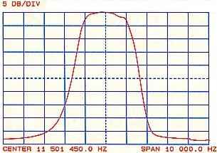
Response | Response (scales expanded). |
Figures 4 and 5 show the spectral response of No 1 unit 11.5 MHz filter. Figure 4 has scales of 1 kHz per division and 5 dB per division whereas figure 5 has scales expanded to 5kHz per division and 10 dB per division. Figure 6 shows the response of No 2 filter with the first scales.
 |
Response (same scales as Figure 4) |
The passband ripple is more pronounced in No 1 unit than in No 2 unit. They were all the same type of crystal but perhaps the No 2 batch were a little better matched than No 1 batch.
Figure 7 shows the capacitance values selected for the 9 MHz filter. This produced the following performance figures:
| Centre Frequency: | 9.049345 MHz |
| 3 dB bandwidth: | 1.94 kHz |
| 6 dB bandwidth: | 2.3 kHz |
| Bandwidth 45 dB down: | 90 kHz |
| Out of band rejection: | 50 dB |
| Passband ripple: | Refer figure 8 |
 |
Circuit diagram. (Capacitor values in pF) |
Figures 8 and 9 show the spectral response of the 9 MHz filter using the same scales as those used for the 11.5 MHz filter in figures 4 and 5.
 |
 |
Response | Response (scales expanded) |
Referring to each of the response curves, the side slopes of the 11.5 MHz units are seen to be much steeper than those of the 9 MHz unit and hence the 11.5 units would make better SSB filters to reject the adjacent sideband. One could offer conjecture as to why the 9 MHz unit did not perform quite as well as the others. Perhaps the crystal Q factors were lower or perhaps the choice of K coefficients was not quite correct. Apart from that, there was one extra crystal in the 11 MHz units to improve the shape.
One observation is that each of the filters produced a 3 dB bandwidth of near 2 kHz for a value of BW2 selected as 2.5 kHz in expression (2). Bandwidth BW2 applies to the two crystal test filter of figure 1 and based on the results achieved, one must conclude that this bandwidth value should be selected around 25% greater than that required for the complete filter with five or six crystals.
Summary
Because of the spread of characteristics in different batches of crystals, one cannot connect up a number of given crystals in a ladder circuit with a pre allocated set of capacitance values and expect to obtain a specific pre-determined performance. Capacitance values must be selected to suit the particular crystals used and the G3JIR procedure outlined is a reliable method of determining these values. The procedure involves the use of some measuring techniques but these are well within capacity of the experimental radio amateur who has access to suitable test equipment.
Providing a cheap source of closely matched crystals can be obtained, construction of the ladder filter is an economical way of obtaining a wide band, but selective filter, for such applications as
SSB.