This is apparently the fixed Switching Panel used to allow the petrol powered "Chorehorse" generator to charge the batteries and power the Wireless Set No.19 in the Chevrolet C8A Heavy Utility Wireless truck. The photograph is used with the kind permission of Paul Bodifee.
Paul and I are both trying to locate one each of these Switchboards for our HUW's. If you can supply any information at all on these, or know where I may be able locate suitable switches to fabricate facimiles of the switchboard, please email me at:-
The switch is a 4-pole knife switch with two fuse holders below. The switch may be made up of two 2-pole switches connected via a common handle. To give an idea of size, I estimate the overall height of the box to be about 12 inches (305mm).
Can you identify this U.S. Army FM receiver?
It covers a similar frequency range to that of the AN/PRC-25 and 77 sets. I would like to obtain a manual or at least a circuit diagram so that I can get it going.
Tom Bryan has pointed me to a document that indicates that this receiver is part of a system called FAAR/TADDS - apparently for Artillery use. Can anyone elaborate on this further or have circuitry or manuals relating to this system?
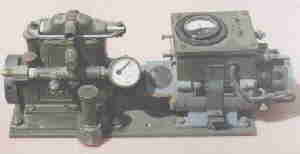
Alco "FIREFLY" Steam powered Battery Charger for the Type 3 Mk.II Suitcase Radio. Used during WW2 by the Resistance Movement in Europe as well as by Australian Commando's (Z-Force) in Borneo. I am looking for handbook (or copy) for this unit.
I am looking for any information or handbooks on this British B-50 Tuner-Amplifier.
Can anyone please identify this key and let me know where it would have been used. The contacts inside are quite substantial and are shunted with a capacitor which has the word "Mansbridge" on it. I guess that's the brand name of the capacitor.
The case is made of cast-iron and has a removable backplate which incorporates the two mounting lugs visible in the photograph. In the center of this backplate, the figure 44 is cast in raised figures.
The connecting cables (2) pass through holes just visible in the vertical raised section and are secured by screws visible on the flat section immediately above.
Any help greatly appreciated.
If you can help with any of the above, please click here
 C8A Heavy Utility Wireless (HUW) Switching Panel
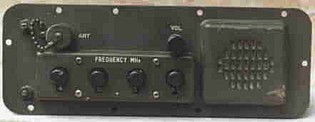 Can you identify this U.S. Army FM receiver?
 Alco "FIREFLY" Steam powered Battery Charger for the Type 3 Mk.II Suitcase Radio. Used during WW2 by the Resistance Movement in Europe as well as by Australian Commando's (Z-Force) in Borneo. I am looking for handbook (or copy) for this unit.
